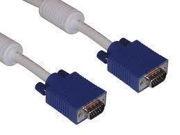
VGA (Video Graphics Array) cables connect computers with monitors or television sets. The cables are based on the graphics standard that IBM developed on personal computers sold during the 1980s. Since that time, almost all personal computers that are built to support the Windows operating system (OS) incorporate support for VGA connections and the more advanced HD connections that have been created and implemented since VGA was first invented.
How do VGA Connections Work?
The term VGA refers to the type of cable used to connect a display to a computer. Most VGA cables have 15 pins on a plug split into three rows of five connectors and two screws located on either side of the pins to secure the socket onto the monitor or computer. VGA cable screws are designed to be hand-tightened without a screwdriver. These cables suffer from signal degradation over distance, resulting in poor picture quality. When a VGA cable is connected between a desktop computer and a monitor, modern OSs are designed to automatically detect the VGA connection. Although many laptops also detect a new video display, many require that the computer’s display be manually sent to the monitor or television by pressing the “Function” and another keyboard key that has a monitor display on top of it to view the connection over the VGA cable.
VGA Standards
VGA specifications require a number of minimum support features in order for the display to properly work. These include support for both 16 and 256 color modes, a minimum of a 262,144 value color pallet that includes six bits each for the red, green, and blue colors, a selectable master clock speed of 25.175 or 28.322 MHz, refresh rates of up to 70 Hz, a vertical blank interrupt, support for a packed-pixel mode of 256 colors, a planar mode supporting up to 16 colors and 4 bit planes, a barrel shifter, and split screen support. Many of these minimum features have been significantly exceeded since IBM originally created the VGA specification, but remain a “lowest common denominator” requirement for VGA support.
VGA Cable (15) Pin Outs
The standard VGA cable has 15 pin outs. They are:
Pin 1 – Red – Red Video
Pin 2 – Green – Green Video
Pin 3 – Blue – Blue Video
Pin 4 – ID2/RES – Reserved since E-DDC, formerly used for the Monitor ID bit 2
Pin 5 – GND – Ground (Hsynch)
Pin 6 – RED_RTN – Red return
Pin 7 – GREEN_RTN – Green return
Pin 8 – BLUE_RTN – Blue return
Pin 9 – KEY/PWR – +5V DC, formerly key
Pin 10 – GND – Ground (DDC, Vsynch)
Pin 11 – ID0/RES – Reserved since E-DDC, formerly the Monitor ID bit 0
Pin 12 – ID1/SDA – I2C data since DDC2, formerly Monitor ID bit 1
Pin 13 – HSynch – Horizontal Synchronization
Pin 14 – Vsynch – Vertical Synchronization
Pin 15 – ID3/SCL – I2Cclock since DDC2, formerly Monitor ID bit 3
The 15-pin VESA DDC2/E-DDC connector pin numbering depicts the arrangements found on the female connector. The mirror image of this design is used on VGA male connectors.
VGA Cable (9) Connector Pinout
The following is the pinout for the 9 pin VGA connector pinout:
Pin 1 – Red – Red Video
Pin 2 – Green – Green Video
Pin 3 – Blue – Blue Video
Pin 4 – HSYNC – Horizontal Synchronization
Pin 5 – VSYNC – Vertical Sync
Pin 6 – RGND – Red Ground
Pin 7 – GGND – Green Ground
Pin 8 – BGRND – Blue Ground
Pin 9 -SGND – Synchronization Ground


vs
Hi..
can you please tell me requirement of 5V (VCC) in VGA cable?