An Introduction to Fault Tolerance
The following issues initiate downtime:
Hardware Failures: Hardware failures can be described as failures that occur in mechanisms like disks or storage media. Hardware failures tend to offset other failures. It is recommended to utilize platforms that can monitor internal temperatures, as well as trigger alarms accordingly. With random access memories, error correcting codes (ECCs) can be utilized to identify and correct single errors and to identify two-bit errors.
-
Software Failures: Determining the reason of a system outage can be quite intricate. Virus protection defects can cause system outages. Often, incorrect system configuration can also lead to system failures.
-
Network Failures: Any changes to the network design or topology of a layer of the protocol stack can have an impact on the entire network. It is therefore better to assess each layer when making any network changes.
-
Operational Failures: Utilizing stringent operational processes will greatly reduce operational failures. Backup strategies and processes should be defined and implemented.
-
Environmental failures are failures that result in data loss or service loss that are brought about by power outages caused by disasters like hurricanes and snowstorms.
Because systems continually change, planning for disaster situations is a continuous process that should occur within an organization. A disaster recovery plan is normally formulated to outline the procedures that should be carried out when disasters occur.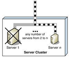
A sound disaster recovery plan is one that incorporates the following:
-
Identifies the potential risks to the organization, and the cost or consequences associated with each identified risk.
-
Identifies the resources which can be used to address each identified risk. Resources can include the following, and be internal or external:
-
Hardware and software
-
Systems
-
People
-
-
Determine the responses or procedures that should be implemented when a disaster situation happens.
-
Test the elements of the disaster recovery plan which can be tested, in a controlled environment. The structure of your organization would affect the manner in which testing is performed.
-
Constantly improve your existing disaster recovery plan.
A few strategies which you can employ to prepare for disaster are listed below:
-
Configure, or set up a fault-tolerant system: A fault tolerant system is a system that is set up in such a manner that it can continue to operate when certain system components experience failures. Fault tolerance pertains to the use of hardware and software to prevent data loss in the occurrence of a failure such as a system or hardware failure. Setting up a fault tolerant system becomes vital when you have servers running mission critical applications. Redundant components, paths and services can be included in the network topology to steer clear of single points of failure, and to ensure a highly available topology.
-
Regularly back up the system: You should back up the System State data on a regular basis. Because the files which are included in System State have certain dependencies, you should back up your System State data as a single unit. Remember that System State data files are unique to a computer running Windows Server 2003. What this means is that you cannot swap System State data files between different servers.
-
Create a boot disk: This involves creating a boot disk which would be used to recover from a situation where an important file is corrupted on the hard disk. Adding or installing the Recovery Console, a new Windows Server 2003 feature, to the boot menu is considered a replacement to creating a boot disk. A boot disk enables you to boot the system when the following conditions are present:
-
Corrupted or missing Ntldr or Ntdetect.com files
-
Corrupted boot sector
-
Corrupted master bot record (MBR)
-
The master boot record (MBR) is infected with a virus.
Install the Recovery Console: The Recovery Console is a new Windows Server 2003 feature that can be used to perform certain recovery tasks when you are unable to use Windows Server 2003 Safe Mode to boot system, such as :
-
Starting and stopping services
-
Copying files
-
-
Create Automated System Recovery (ASR) disk sets through the Windows Backup utility. The ASR disk includes important data which can be utilized to repair the following important components:
-
The boot sector
-
System files
-
The startup environment
-
-
Configure Recovery Options in the System tool in Control Panel that defines the manner in which Windows should handle system failures/crashes.
A few strategies which you can employ to ensure fault tolerance in your system are summarized below:
-
To enable your servers to shut down properly when a power failure occurs, use an uninterruptible power supply (UPS).
-
To ensure that no data is lost when a hard disk failure occurs, deploy one or multiple RAID arrays for both system and data storage. This ensures that only the failed disk needs to be replaced when a disk failure occurs. RAID essentially adds fault tolerance to file systems, and increase data integrity and availability because it creates redundant copies of your data. RAID can be used to improve disk performance as well.
-
To provide redundancy for SCSI controller failures, you should utilize multiple SCSI adapters.
-
To provide redundancy for network card failures, utilize multiple network cards.
-
To cater for server failures where a server holds mission critical data, or runs mission critical applications, utilize clusters to provide redundancy and failover.
Understanding the Mean Time to Failure and Mean Time to Recover metrics
The metrics utilized to measure fault tolerance are:
-
Mean time to failure (MTTF): This is the mean time to a device failing
-
Mean time to recover (MTTR): This is the mean time which will be needed to recover after a failure has taken place.
The calculation typically used to measure downtime is:
-
MTTR/MTTF
There are three phases to devices' life cycle with every phase being categorized by a particular behaviour:
-
Burn-in phase: At this phase, failures occur quite often. Burn-in failures typically decrease quite fast as well.
-
Normal Aging phase: Devices rarely fail in this phase. A device's attributes can be monitored once in the normal aging phase to pinpoint behavior associated with defined rates of failure. The failure rate of devices can also be monitored and followed so that they can be swapped before the failure mode phase.
-
Failure Mode: Failures tend to increase more rapidly as the devices lifespan increases.
A few factors to consider when working with the MTTF and MTTR metrics are listed below:
-
Electronic components typically have a high failure rate during its burn-in phase or early lifetime period. After this period, the failure rate of the component stays constantly low, and only significantly changes when the component nears the end of its lifespan. At this time, the failure rate of the component increases.
-
The common MTTF for a commodity hard disk is usually 35 to 50 years. For server specific hard drives, it is 134 years.
-
For the points of failure which you have identified in your disaster recovery plan as being most costly, try to reduce the MTTR. Clustering can be implemented to decrease MTTF
Safeguarding the Power Supply
The power supply is considered the biggest failure point for a network, simply because computers cannot run without power. A network should be protected from the following power supply issues:
-
Local or internal power supply failure: Because the failure of the local or internal power supply on a server, router, or network hardware component has catastrophic consequences, the majority of servers include a redundant power supply. For those servers that do not include a redundant power supply, the option normally exists to include one. It is strongly recommended to use this option for your servers. You should also include the replacement of power supplies of any critical hardware as part of the disaster recovery plan.
-
Voltage variations: Voltage variations include the following:
-
Spikes: These are rather large brief increases in voltage which are usually caused by external factors (lightning strike). Spikes can however also be caused by internal factors, such as when starting a large piece of equipment. To protect your network from spikes, purchase surge protectors that are designed to safeguard the network. They work by detecting a large increase in voltage, and then creating another electrical path for this voltage. In this manner, the increase in voltage does not reach the servers.
-
Surges: Surges are normally not as large as voltage spikes, but they last longer. Most constant voltage transformers can deal with surges.
-
Sags: Sags occur when there is temporary reduction in the voltage which can actually result in a server that is not protected from voltage sags, rebooting. You can protect your servers from damage caused by sags by utilizing a good UPS or a constant voltage transformer.
-
Brownouts: These are planned reductions in voltage, normally by 5 to 20 percent from the normal value, which are initiated by the electric company. To protect against the effects of brownouts, use a UPS or a constant voltage transformer. A constant voltage transformer that can support all critical devices and servers can offer protection against extended brownouts.
-
-
Short-term power outages: These are your external power failures which last from a few fractions of a second to a few minutes. Short-term power outages can be caused by both internal and external factors. You can seldom plan for short-term power outages – any unprotected servers either simply reboot, or they fail. To protect your servers from short-term power outages, use a UPS together with good spike protection.
-
Long-term power outages: These are your power failures which last from a few minutes to several hours, or even several days. Long-term power outages are typically caused by external factors such as earthquakes, storms, or fires.
Providing Fault Tolerance through RAID Arrays
The hardware failure that normally occurs most frequently is a hard disk failure. To protect data from drive failures and to add fault tolerance to your file systems, use RAID technology. Windows Server 2003 provides good fault-tolerant RAID systems. Windows Server 2003 also supports hardware based RAID solutions.
You can implement fault tolerance as hardware based RAID, or software based RAID. Windows Server 2003 provides a software implementation of RAID to maintain data access when a single disk failure occurs. Data redundancy occurs when a computer writes data to more than one disk. This in turn safeguards data from a single hard disk failure. The distinction between software RAID and hardware RAID is that software RAID is put into operation solely through software and needs no special hardware for it to be implemented. Hardware RAID uses special disk controllers and drives. Hardware RAID is more fault tolerant than software RAID. It is also simpler to recover from failure when RAID is implemented in hardware than the software RAID provided by Windows Server 2003. While software RAID is simple to set up and configure, it has shortfalls. A hardware RAID system can rebuild itself more rapidly than what software RAID can. When a drive has a failure, the server does not need to be brought down to replace the particular drive. You can hot swap the failed drive. With software RAID, if one of the drives in a stripe has a failure, the server has to be brought down before you can replace the failed drive.
Windows Server 2003 supports three levels of RAID, namely, RAID 0, RAID 1 and RAID 5.
The RAID levels available to enable fault tolerance are listed below:
-
RAID 0: You can use disk striping without parity, RAID 0, if you want to utilize space on multiple disks and simultaneously improve read and write performance. In Windows Server 2003, a RAID 0 volume is known as a striped volume. RAID 0 provides no fault tolerance. The data in the entire volume is lost if a disk in a striped volume fails.
-
RAID 1: A RAID 1 volume is known as a mirrored volume. Two disks partake in a mirrored volume. This configuration is also known as a mirror set. With mirroring, two copies of all data are written to separate volumes on two different disks. In the case where one disk fails, the remaining disk in the mirror volume set has an identical copy of the data. It is good practice to mirror the boot and system volume to ensure that you can boot the server in the event of a single drive failure. Disk mirroring provides almost the identical fault tolerance as disk striping with parity (RAID 5).
-
RAID 3: With RAID 3, or byte-level parity, data is split at the byte level and striped across multiple drives with the parity information written to a single dedicated drive. The parity information is stored on a single drive rather than it being striped over all the drives. Data loss does not occur when a disk failure happens. The parity information and the data on the remaining operating drives are used in a mathematical calculation to reconstruct the data that is lost. There is however a significant loss of performance.
-
RAID 4: RAID 4 or block-level parity is similar to RAID 3, with the difference being that data is striped over multiple disks in blocks. A dedicated parity disk is used for the parity information. A RAID hardware controller is required for RAID 4.
-
RAID 5: RAID 5, or disk striping with parity, uses disk striping with parity. RAID 5 needs at least 3 hard disks to implement fault tolerance. To enable fault tolerance, RAID 5 writes parity information with the blocks of data. Whenever data is written to RAID 5 volumes, it is written across all the striped disks in the RAID 5 volume, and parity information for the data is also written to disk. Parity information is written to a separate disk from that disk holding the matching data. The parity information is then used to recover the data when a disk in the striped set fails. The RAID 5 set continues to function at this point because the remaining disks deals with disk functions. However, when two disks in the RAID 5 volume set fails, the parity information is inadequate to recover the data.
-
Nested levels of RAID: Nested levels of RAID make use of a grouping of the single levels of RAID. An example of a nested RAID level is RAID 1+0, which is commonly also known as RAID level 10. With RAID level 10, data is striped across mirror sets, thus combining the fault tolerance of RAID 1 with the fast read and write performance provided by RAID 0.
The factors that should be included when you determine which RAID solution suites the fault tolerance requirements of your organizations are:
-
The intended use of your applications plays an important role in determining which RAID solution to implement. Elements to include under intended use are whether the applications you are running are read intensive or write intensive, and whether the applications uses data sequentially or randomly.
-
The performance of each level of RAID is affected by intended use. Factors to clarify under performance are to determine whether the server is excessively utilized or not, and whether your applications are I/O intensive.
-
The level of fault tolerance provided by the different levels of RAID is another important element to consider. All RAID levels, other than RAID 0, provide some form of fault tolerance. What you need to consider is the way in which each level can handle any subsequent failures.
-
The level of availability provided by each level of RAID is also important. You should decide whether your servers require high availability, or whether they can afford to be offline.
-
The costs associated with implementing the different RAID levels differ. As mentioned previously, hardware based RAID solutions cost more than software based RAID solutions. Software based RAID in Windows Server 2003 is considerably cheaper than implementing hardware based RAID solutions.
Understanding Clustering Technologies
Microsoft offers the following two clustering technologies that are supported in Windows 2000 and Windows Server 2003.
-
The Microsoft Cluster Service – cluster servers
-
The Network Load Balancing (NLB) Service
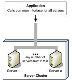
Microsoft Clustering Server (MSCS), initially launched in the Windows NT Server Enterprise Edition, enabled organizations to increase server availability for mission critical resources by grouping multiple physical servers into a cluster. Servers in the cluster are referred to as nodes, while services and applications are referred to as resources. A cluster can be defined as the grouping of two or multiple physical servers that are portrayed as, and operate as one network server. These servers provide redundancy to the enterprise network by resuming operations of a failed server within the cluster. This procedure is known as failover. The process of failback occurs when a failed server automatically recommences performing its former operations once it is online again. The cluster can also be configured to provide load balancing features. With the introduction of Windows 2000 this technology became known as Microsoft Cluster Service. Microsoft Cluster Service is best suited for network services that require a high degree of availability. Windows Server 2003 can support eight node server clusters.
Resource DLLs manage resources in the cluster, and provide the mechanism for Cluster Service to maintain communications with its supported applications. A quorum resource has to exist in order for a node in the cluster to carry out its functions. This common resource holds the cluster database's synchronized version that stores management data for the cluster. The quorum resource is situated on the physical disk of the shared drive of the cluster. Clustering software such as resources makes is possible for the cluster to operate. Administrative software is the software utilized to manage the cluster, such as Cluster Administrator.
A few advantages associated with deploying cluster servers are:
-
Clustering technology provides redundancy for network failures because another node is the cluster resumes the services of the failed server. This increases server availability for mission critical applications and network services.
-
Application response time can be improved by dispersing applications across multiple servers.
-
There is no manual configuration associated with failback because the failed server automatically takes on its former operations.
-
Cluster Service also reduces downtime associated with scheduled maintenance downtime. When a server in the cluster is scheduled for an upgrade, its services and applications can be manually moved to another node in the cluster.
-
A network utilizing Cluster Service enjoys improved scalability because servers can be expanded while client access is still ensured.
-
The nodes, services and applications in the cluster can be managed, controlled and administered remotely, and in the same manner as though they were all hosted on one server.
The installation requirements of Cluster Service are listed below:
-
For Cluster Service installation, you need to have administrative permissions on each node in the cluster.
-
There should be sufficient disk space on the system drive and shared device for Cluster Service installation.
-
Verify that the network adapters have the proper TCP/IP configurations, and that the appropriate network adapter drivers are being utilized.
-
File and Print Sharing for Microsoft Networks has to be installed on a node in order to configure Cluster Service.
-
The nodes should be configured with the same hardware and device drivers.
-
Each cluster node has to be part of the same domain, and the domain account utilized should be identical on each cluster node.
-
Before installing any additional nodes for the cluster, first ensure that the previously installed node is running.
-
The system paging file should have sufficient space to prevent decreased performance. When the file has insufficient space, it can result in a system lockup at installation.
-
It is good practice to examine the system and event logs prior to, and after installing Cluster Service.
-
You can use System Monitor to troubleshoot virtual memory issues.
When determining the applications for the cluster and failover, consider the following:
-
The application has to utilize Transmission Control Protocol/Internet Protocol (TCP/IP), or Distributed Component Object Model (DCOM) and Named Pipes, or Remote Procedure Call (RPC) over TCP/IP to function in the cluster.
-
NTLM authentication must be supported by the application.
-
To be included in the failover process, an application has to be capable of storing its data on the disks connected to the shared bus.
-
Applications installed on the cluster are categorized as either cluster aware applications, or cluster unaware applications. When an application supports TCP/IP and transactions; and stores its data in the conventional way, it is implemented as a cluster aware application. File applications, and client database applications are categorized as cluster aware applications. Cluster unaware applications do not interrelate with the cluster, although they can be configured for basic cluster capabilities. This is done by creating an application specific resource DLL for the cluster unaware application. This would ensure that the cluster unaware application starts and terminates properly when the cluster fails.
Cluster implementations offer a choice between five configuration models. The configuration model chosen affects cluster performance, and the degree of availability ensured during a failure. The different configuration models are:
-
Virtual Server Configuration Model: A single node exists in the cluster. No failover capabilities exist in the cluster. Virtual servers can be implemented to respond to clients' requests. At a later stage, when additional nodes are implemented for the cluster, resources can be grouped into the virtual servers without needing to reconfigure any clients.
-
High Availability with Static Load Balancing Configuration Model: The nodes each have particular resources that they are accountable for. To ensure availability during failover, each node has to be sufficiently capable of supporting another node's resources. This configuration model leads to decreased performance for the duration of the failover.
-
Hot Spare Node with Maximum Availability Configuration Model: A single primary node manages the resources. The hot spare node is not utilized at the same time as the primary node. This node only manages the resources when the primary node has a failure. This model ensures high availability and high performance during failover.
-
Partial Cluster Service Configuration Model: This model builds on the principles of the former model. When failover occurs, the cluster unaware applications stay unavailable for the duration of the failover. Cluster unaware applications are not part of this process and performance for these applications is greatly reduced at times of failover. This configuration model provides high availability for resources that are included in the failover process.
-
Hybrid Configuration Model: This model can be regarded as a grouping of the above configuration models. I this configuration model, each node in the cluster manages its own resources. Because this model is a grouping of the other models, availability during failover is ensured for those resources specified for failover.
Windows 2000 Network Load Balancing (NLB) is a clustering technology that provides high availability and scalability. NLB is typically utilized to assign Web requests between a cluster of Internet server applications. NLB reroutes any requests that are sent to a failed NLB cluster server. With NLB, client requests are load balanced according to the configured load balancing parameters. Servers in the NLB cluster can therefore be configured to share the processing load of client requests. The Wlbs.sys driver of NLB is configured for each server in the cluster, and functions between the network adapter and the TCP/IP protocol. The driver manages and allocates client requests to a server in the cluster. With NLB there is no single instance of failure purely because it is regarded as a distributed application. Throughput is maximized because the broadcast subnet is utilized to distribute client requests to the cluster servers. These client requests are then filtered on each cluster server.
To ensure high performance, NLB uses a distributed filtering algorithm to match incoming client requests to the NLB servers in the cluster when making load balancing decisions. When an incoming packet is received, all the NLB servers check to determine which NLB server should handle the client request. The NLB servers use a statistical mapping that determines a host priority for the incoming packet, to identify the NLB server that should handle the request. Once the NLB server is identified for the packet, the remainder of the servers in the NLB cluster discards the packet. Each server in the NLB cluster utilizes and transmits heartbeat messages to identify the state of the cluster. The heartbeat message holds information on the state of the cluster, and the cluster configurations and associated port rules.
A few NLB planning considerations and requirements are listed below:
-
The applications in the cluster have to utilize TCP or UDP ports, and clients have to be able to connect utilizing TCP/IP.
-
It is recommended to have two network adapters per cluster host.
-
The hosts in the cluster should be on the identical physical subnet.
-
NLB can be utilized with VPN servers and streaming media servers.
-
You should plan server capacity according to the different types of applications that are going to reside in the NLB cluster.
-
Add servers to the NLB cluster until the client request load is manageable, and does not overload the cluster. Up to 32 servers can exist in a NLB cluster.
-
Hardware based RAID or software based RAID can be utilized to provide disk fault tolerance.
-
The servers should be configured correctly to run and support the applications hosted on them; and all applicable applications should be load balanced. The majority of applications that can be configured to utilize TCP/IP with the relevant port can partake in load balancing in the NLB cluster. The applications which are generally supported in a NLB cluster are:
-
SMTP
-
HTTP
-
HTTPS
-
FTP
-
TFTP
-
Understanding the Role of Distributed File System (Dfs) in Fault Tolerance
Distributed file system (Dfs) is a single hierarchical file system that assists in organizing shared folders on multiple computers in the network. Dfs provides a single logical file system structure, and can also provide a fault-tolerant storage system. Dfs provides load balancing and fault tolerance features that in turn provide high availability of the file system and improved performance. Administrators can also install Dfs as a cluster service to provide improved reliability. With domain based Dfs roots, Active Directory is used for the Dfs topology replication, thereby ensuring fault tolerance and the synchronization of the fs root and shared folders. Configuring replication for the Dfs root and the individual shared folders provide improved performance to clients. With added load balancing, clients can randomly select a physical server to connect to using the list of referrals provided by the Dfs server.
Dfs roots can be either stand-alone roots or domain based roots.
-
The characteristics of stand-alone Dfs roots are highlighted below:
-
Standalone Dfs roots can exist on any Windows server.
-
Stand-alone Dfs roots do not use Active Directory because the Dfs information is stored in the local registry.
-
Stand-alone Dfs roots provide no automatic replication features for the Dfs roots, and shared folders, thereby making the Dfs root a single point of failure. Although file replication services are unavailable with stand-alone Dfs roots, you can create a replica from the Dfs root.
-
-
The characteristics of domain based Dfs roots are highlighted below:
-
Domain based Dfs roots exist on a member server or on a domain controller belonging to an Active Directory domain.
-
Domain based Dfs roots use Active Directory services to store the Dfs tree topology. A domain based Dfs root does not represent a single point of failure because the Dfs topology is published in Active Directory.
-
Targets are automatically synchronized by Active Directory services when changes are made to the Dfs tree.
-
Domain based Dfs roots must be located on a NTFS version 5.0 formatted partition.
-
With Windows Server 2003, a server can host multiple domain based Dfs roots.
-
The following servers can host a Dfs root, or be a Dfs server:
-
Any one of the editions of Windows Server 2003
-
Windows 2000 server
-
Windows NT 4 Server with SP3 or later
The process for deploying domain based Dfs is briefly outlined below:
-
Identify those servers that are going to host Dfs roots. The servers have to be member servers, or domain controllers of the domain.
-
You have to create a shared folder on the Dfs server that is to serve as the Dfs root. You should keep files within the linked shares, and not in the particular volume.
-
Create the actual Dfs root
-
Specify any additional root targets
-
Create the Dfs links to the shared folders. You can also add links to shared folders on other servers.
-
Specify any additional link targets
How to create a striped volume (RAID 0)
-
Open the Disk Management console
-
Right-click the unallocated space on the disk where you want to create the volume, and select New Volume to launch the New Volume Wizard. Click Next.
-
Select Striped on the Select Volume Type window. Click Next.
-
On the Select Disks window, select the disk(s) to include in the striped volume, and the amount of space to be used. Click Next
-
On the Assign Drive Letter or Path window, assign a drive letter or mount the volume to an empty NTFS folder. Click Next
-
On the Format Volume window, select a format (NTFS) for the volume, or select the Do not format this volume option. Click Next
-
The Completing the New Volume Wizard window displays the options you have selected.
-
Click Finish to create the striped volume.
How to create a mirrored volume (RAID 1)
-
Open the Disk Management console
-
Right-click the volume you want to mirror, and select Add mirror to open the Add Mirror window.
-
Select the disk you want to use for a mirror.
-
Click Add Mirror to create the mirror.
How to recover from a mirrored volume failure (RAID1)
-
Open the Disk Management console
-
Right-click the failed mirrored volume and select Remove Mirror from the shortcut menu.
-
When the Remove Mirror dialog box is displayed, choose the disk that should be removed, and click Remove Mirror
-
Click Yes to verify your action to remove the mirror. The remaining volume turns into a simple volume.
-
You can now remove the failed drive from the computer, and replace it.
-
Following this, you should use the Disk Management console to create the mirrored volume again
How to create a RAID 5 volume
-
Open the Disk Management console.
-
Right-click the unallocated space on the disk where you want to create the RAID 5 volume, and select New Volume to launch the New Volume Wizard. Click Next.
-
Select RAID 5 on the Select Volume Type window. Click Next.
-
On the Select Disks window, select the disk(s) to include in the volume, and the amount of space to be used. Click Next
-
On the Assign Drive Letter or Path window, assign a drive letter or mount the volume to an empty NTFS folder. Click Next
-
On the Format Volume window, select a format (NTFS) for the RAID 5 volume, or select the Do not format this volume option. Click Next
-
The Completing the New Volume Wizard window displays the options you have selected.
-
Click Finish to create the RAID 5 volume
How to recover from a RAID 5 volume failure
-
Back up your data prior to performing any necessary actions to repair a RAID 5 volume set.
-
Your first step is to restore all drives in the RAID5 volume set to online. The status of the volume set has to be displayed as Failed Redundancy.
-
Where the status of the failed volume is Missing or Offline, verify that the drive has power and that there are no connectivity issues.
-
Use the Disk Management console to reactivate the disk. Right-click the volume and then choose Reactivate Disk from the menu. The status of the drive should first move to Regenerating and following this, to Healthy.
-
Right-click the volume and choose the Regenerate Parity option if the status fails to change to Healthy.
-
Where the status of the failed volume is Online (Errors), right-click the volume that failed and choose Reactivate Disk from the menu. The status of the drive should first move to Regenerating and following this, to Healthy. Choose the Regenerate Parity option if the status fails to change to Healthy.
How to configure a DHCP cluster
-
Install the cluster hardware
-
Proceed to configure Cluster Service
-
Install the DHCP service on the node in the cluster
-
Specify the global options when implementing many scopes.
-
Configure a new scope. Assign the IP Address range and options (WINS/DNS server). Next, define and set any further scope options.
-
Any necessary reservations can now be specified for clients needing a reserved IP Address. Remember to exclude IP Addresses that are not part of the lease.
-
Proceed to activate the new scope.
-
Any option classes and additional option types can be allocated next.
-
The lease duration can also be modified as required.
-
If multiple subnets are going to be supported, superscopes should be configured next.
-
Next, authorize the DHCP server in Active Directory. Configure the DNS dynamic update policy.
-
When supporting routed networks, DHCP or BOOTP relay agents might need to be configured. The BOOTP table needs to be configured.
-
Any multicast scopes (if necessary) can be configured next.
-
Configure a resource group for the DHCP resources. Utilize the New Group Wizard provided by Cluster Service.
-
Launch the New Resource Wizard provided by Cluster Service to define the necessary IP Address, Network Name and Dependant Disk resources.
-
Next set the database, and backup and audit paths' locations for the DHCP resource on the shared device
-
Verify failover for the DHCP cluster, and check whether the DHCP server can be accessed by clients.
-
You can use System Monitor to monitor DHCP Server performance. The DHCP Server audit log can be utilized for troubleshooting purposes.
How to install Internet Information Services (IIS) on a cluster
-
On the cluster shared disk, configure a folder for the IIS virtual servers. A folder should be configured for each IIS virtual server.
-
Next, utilize Cluster Administrator to configure a resource group for each defined virtual server. For this, the Dependant Disk resource for each resource group is necessary. The Dependant Disk resource for MS DTC (if configured) should be the same as the IIS virtual server disk.
-
Ensure that the IIS virtual server resources are on the node that manages the Physical Disk resource of the virtual web.
-
Configure the IIS virtual server's IP Address resource in the exact group as the Physical Disk resource at the location of the Web folders. Configure the IP Address resource as being dependent on the IIS virtual server's Physical Disk resource and MS DTC resource (if necessary).
-
Specify the IIS virtual server's Network Name in the exact group as the Physical Disk resource at the location of the Web folders.
-
Configure the Network Name resource as being dependent on the IP Address resource.
-
To configure the cluster Web site, utilize the Internet Services Manager snap-in. The cluster Web site can be a new Web site or an existing Web site. The Web site should utilize the IP Address and folder on the shared disk. Make certain that the Web site is not specified as All Unassigned, or to the IP address of the IIS virtual server. The Website has to utilize an anonymous username/password combination. The nodes have to be able to utilize these details.
-
Next, continue to configure the identical Web site on the other cluster node.
-
Configure an IIS server instance with the Web site value mapping to the IIS Web site. Utilize Cluster Administrator for this configuration. For failover, ensure that each node is a possible owner of the IIS server instance, and that an IP address resource dependency is configured. When the Web information is held on the cluster, the IIS server has to be dependent on the Physical Disk resource. A Network Name dependency can be configured. This will ensure failover when the network name is utilized for accessing purposes.
-
It is recommended to utilize Cluster Administrator to start and stop the cluster Web sites / IIS resources. Cluster Administrator should also be utilized to remove cluster IIS resources.
-
All IIS resources have to be removed from the node before you uninstall Cluster Service.
How to create a domain based Dfs root
-
Open the Dfs console
-
Right-click the Distributed File System icon, and choose New from the shortcut menu. You can also select the New Root option from the Action menu
-
When the New Root Wizard launches, click Next on the Welcome To The New Dfs Root Wizard screen.
-
On the Root Type screen, choose the Domain Root option if the server is a member of an Active Directory domain. Click Next
-
Enter the fully qualified DNS name of the server hosting the Dfs root on the Host Domain screen. You can click Browse to search Active Directory for the server. Click Next
-
When the Root Name screen appears, enter a name for the new Dfs root. You can also enter a comment in the Comments field. Click Next
-
The Root Share screen is displayed when the share does not exist on the server. This is where you enter the full path to the folder that should store the Dfs root. Click Next
-
Verify the settings that you have selected
-
Click Finish
-
The wizard now shares the specified folder, and creates the Dfs root and entries in the registry.
How to publish domain based Dfs roots in Active Directory
-
Open the Dfs console
-
Choose the Dfs root, and select Properties from the Action tab.
-
When the Properties dialog box of the selected Dfs root appears, click the Publish tab.
-
Enable the Publish This Root In Active Directory checkbox
-
Enter a description for the Dfs root in the Description box
-
You can also enter an e-mail address for the administrator of the Dfs root in the Owners box
-
Click the Edit button to specify a list of keywords.
-
Click OK.
How to create Dfs links
-
Open the Dfs console
-
In the left pane, choose the root that you want to create a link(s) for.
-
Select the New Link option from the Action menu.
-
The New Link dialog box opens.
-
Enter the name that you want your users to see when they browse Dfs in the Link Name box.
-
In the Path To Target box, enter the shared folder's UNC or DNS path. You can alternatively click the Browse button.
-
Use the Comments box to enter any additional information.
-
In the Amount Of Time Clients Cache This Referral In Seconds box, enter the amount of time for clients to cache the referral before they ascertain whether it is still valid.
-
Click OK.
How to create targets for the Dfs root to provide redundancy
When working with domain based Dfs roots, you can configure the Dfs root with targets to provide redundancy. By setting up multiple targets for the Dfs root, you are enhancing fault tolerance for the Dfs tree. Targets can also be configured to automatically replicate with one another. You can ensure that users can continue to access files when a server has a failure by creating additional targets for your Dfs links.
To create targets for the Dfs root
-
Open the Dfs console
-
Navigate to the domain based Dfs root that you want to add targets for.
-
Select the New Root Target option from the Action menu
-
This action initiates the New Root Wizard.
-
Enter the DNS name of the server that is going to host the new target. You can click Browse to find the server. Click Next
-
Enter the path of the folder that you are going to use for the Dfs root target. You can click Browse to find the folder. Click Next
-
Verify the settings that you have specified.
-
Click Finish
-
The new Dfs root target is created.
aravind
may i know the tools to find fault tolerance in server plz…