The Universal Serial Bus (USB) interface connects peripherals in a variety of ways. These peripherals include the standard and non-standard computer mouse, keyboards, gaming controllers, scanners, printers, digital cameras, hard disks, CD/DVD-Rom drives, card media devices, music devices, speakers, and networking components. A variety of other devices that use USBs as well as devices that may use the USB pinout design to provide power, access data, or distribute the connections are available.
Standard USB 1.1 can output data at 12Mbit/s, while USB 2.0 can output up to 480Mbit/s. This large increase in speed is possible if the computer’s USB host controller and the device are capable. Otherwise, the USB device’s speed will function at USB 1.1.
What is the USB Pinout Configuration?
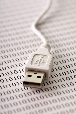
The USB connections have 4 pinouts. They are numbered 1-4 and are used for a variety of reasons.
Pin 1 is the VCC or Common Collector Voltage that is used for power. A red wire connects to pin 1 and provides the positive voltage from the source connection (+5V).
Pin 2 is the USB Data positive pin (D+) that has a white wire connected to it and provides the correct flow of positive data signals from the device (when applicable).
Pin 3 is the USB Data negative pin (D-) that has a green wire connected to it and provides the correct flow of negative data signals from the device (when applicable).
Pin 4 is the Ground pin (GND) and has a black wire connected to it. This ground wire prevents electrical buildup and provides a neutral reservoir for such energy to exit to instead of to a device.
These pins are designed to allow communication between the device and the host controller. This could be anything from the transfer of data between the device and the host to charging the device from the host controller port. How the host controller communicates with the device depends on the type of device and pins that are used in it.
A USB hub is a type of splitter for USB connections. Hubs can be connected to other hubs in multiple levels and may connect 127 devices through a single USB host controller port. Since it is possible to have so many different types of connections through a single port, it is also possible for the various devices that use the port to interact with the computer. The USB has become an unofficial standard in home computing due to the versatility of the connection and the speed associated with it.
The USB interface was designed to connect many different devices without having to provide additional pieces of hardware such as PCI/PCI-Express bus cards. The devices’ ability to plug and play provided hot swapping capabilities through the USB without having to restart the system to recognize the devices.
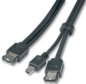
Types of USB Pinout Connector Packaging
USB pinout connectors are designed for different devices’ use. There are six main types of connectors. There are several different non-standard connectors that are specially designed for devices with proprietary formats or parts that are unique to the device. This is done in order to prevent users from using unapproved wires with their devices (which may damage the device).
The six types are:
USB-Plug/Jack A – This is the standard USB rectangular interface that is used as the host controller connector. Other devices may use this type of connector, which makes it possible for generic cables to be used with the device.
USB-Plug/Jack B – This is a square looking connector that is tapered on one side to show the orientation of the connection. The jack is built similarly and is used most commonly with devices such as printers and scanners.
The USB A and B plugs/jacks are designed with only 4 pins. The mini and micro USB connectors/jacks may have 1-4 extra pins depending on the device and the host controller’s standard interface.
USB-Mini-Plug/Jack A – The mini A connector/jack is much smaller and has a tapered end to help find the orientation of the cable and jack. It is used in many mobile devices for data transfer and power.
USB-Mini-Plug/Jack B – The mini B connector/jack is more common with devices and can be found in many different configurations.
USB-Micro-Plug/Jack A – The micro A is much smaller and is commonly used with smaller devices. It is one of the new standardized options for mobile phones.
USB-Micro-Plug/Jack B – Similar to the micro A, B is also used in smaller devices and has a different type of jack/plug. It looks like a smaller version of the mini A.
Configuration of USB Powered Devices
The USB pinout that provides power is usually designated to the first pin. This power source is designed to offer 5 volts. A hub can provide up to 500mA to each device connected to it. The devices must share the power unless an external source of power is added to break the 500mA limit on the hub itself. A device cannot use more than the port’s power limit.
USB devices communicate their power requirements to the host controller. When one hub’s power limit is exceeded, the computer OS usually relays this information and the possibility of removing some devices to accommodate others.
The USB devices’ power usage are as follows:
Bus Powered Hubs – The device draws a maximum of 100mA at the power up and 500mA under normal conditions.
Self Powered Hubs – The device draws a maximum of 100mA and must supply 500mA to each port for proper distribution of power.
Low Power, Bus Powered Functions – The device normally draws a maximum of 100mA.
High Power, Bus Powered Functions in Self Powered Hubs – The device draws a maximum of 100mA and must supply 500mA to each port in the hub.
Self Powered Functions – The device draws a maximum of 100mA.
A Suspended Device – Has a maximum of 0.5mA power supplied while in suspension.
Powering USB Devices
A USB Charger shorts the 2 Data lines together with Dedicated Charger Mode. The data cannot be transmitted or received from this connection but the device can receive up to 1.8A through the power supply.
Voltage that the host or a powered hub supplies is within the 4.75 and 5.25 volt range. Normal operating voltage is at the minimum of 4.75 volts, which the VCC wire provides. When working at low power, the voltage can be as low as 4.4 volts with a maximum drop of 0.35 volts from the minimum normal working voltage.

Follow Us!