Redundant Topology
A Local Area Network may consist of more than one segment. Each segment of the LAN connected through a separate physical device mostly switch. Switches use their uplink ports to connect different segments. The LAN administrator can connect the switches with each other through more than one uplink port using redundant topology. Redundant topology eliminates the single point of failure and that will improve the performance of network. Overall redundant topology is a good solution for making a LAN efficient but there are some drawbacks of redundant topology. It causes broadcast storms, multiple frame copies and MAC address table instability problems. For example there are two switches connect with each other using redundant topology. A host on one segment sends a broadcast frame. Broadcast frames are flooded to all ports other than the originating port. Remembering redundant topology, there are two uplink ports are using on both the switches, so the switches continue to propagate the broadcast traffic over and over through the uplink ports. Complex topology can cause multiple loops to occur and layer 2 has no mechanism to stop the loops. The solution is Spanning Tree Protocol.
Spanning Tree Protocol Basics
The IEEE defines the Spanning Tree Protocol that provides a loop free redundant network topology by placing certain ports in the blocking state. STP works in a broadcast domain therefore each VLAN has its own spanning tree. Spantree 1 is by default enabled in the Cisco switches for the default VLAN 1. A switch as compare to bridge may have multiple spanning tree protocols as the number of VLAN while Inter VLAN routing supports ip spanning.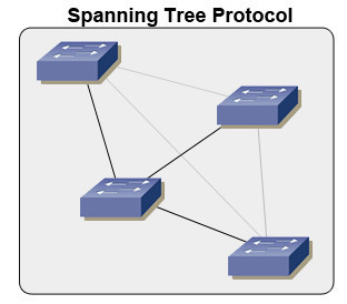
How Spanning Tree Protocol Works
The spanning-tree operations are as follows:
-
STP elects a Root Bridge and both the ports of the Root Bridge are designated ports and are placed in the forwarding state.
-
The non Root Bridge considers one of its ports as a root port with the least administrative cost and the other port considers as a non designated port. Root port placed in the forwarding state in the blocking state while the non designated port is in the blocking state.
Spanning Tree Protocol AlgorithmThe STP algorithm selects the Root Bridge first:
-
Root Bridge is the switch with the lowest Bridge ID and Bridge ID consists of bridge priority and MAC address. The lowest bridge priority chosen first, the default bridge priority value is 32768; if the bridge priority is same then the lowest MAC address will be chosen.
-
Messages are sent to each switch through BPDU frame. The Bridge Protocol Data Unit (BPDU) frame is also called Hello. By default, Hello messages are sent after every 2 seconds.
-
If a switch receives BPDU that is lowest then its self, the switch forwards that BPDU, claiming it to be the root port.
-
Cost is calculated by adding the cost in the received BPDU to the cost of the interface the BPDU was received.
How STP Handles the Network Topology Changes? -
Hello time: The time root waits before sending periodic Hello BPDU that are forwarded by the other switches. By default, it is 2 seconds.
-
Max Age: The time any switch should wait before trying to change the STP topology after unhearing Hello BPDU.
-
Forward Delay: The delay time an interface takes to converge from blocking state to forwarding state.
STP Operation Summary -
The root sends hello BPDU frame out of all interfaces.
-
Neighbour switches forward hello frames out of their non root designated ports, identifying root, with their cost added.
-
If a switch does not receive BPDU frame, continues as normal until Max Age.
STP ConvergenceThere are four port states concern with STP topology convergence:
-
Blocking
-
Listening
-
Learning
-
Forwarding
Switch wats Max Age time, place in the listening state for Forward Delay time, place in the learning state for Forward Delay time and then place in the forwarding state. Switch must also timeout entries in MAC address table.
-
Max Age: 20 seconds (blocking to listening)
-
Forward Delay: 15 seconds (listening to learning)
-
Forward Delay: 15 seconds (learning to forwarding)
Optional Convergence Features of STP -
EtherChannel: provides a way to prevent STP convergence from being needed when only a single port/cable failure occurs. It combines from 2-8 parallel Ethernet trunks between same pair of switch, which STP treats as a single link. It also provides more bandwidth. Both links to the same switch must fail for a switch to need STP convergence.
-
PortFast: Allows a switch to place a port in the forwarding state immediately when the port becomes physically active (only safely done when device is not a bridge/switch)
-
Cisco BPDU Guard Feature: If enabled, tells the switch to disable PortFast ports if BPDU is received on those ports.
Rapid Spanning Tree ProtocolThe Intel pro set IEEE Rapid Spanning Tree Protocol (RSTP) can be used alongside 802.1d STP for switches that support RSTP. The assignment of forwarding and blocking ports are same in both STP and RSTP, the main reason to use RSTP is to overcome the convergence time and therefore it supposes the spanning tree best practice.
RSTP Convergence
The RSTP convergence time is typically less than 10 seconds as compare to the traditional convergence time of 50 seconds. In case of link between switch and a hub that is called Link-Type shared, RSTP does not improve convergence.
Optional Convergence Features of RSTP
-
Edge-Type Point-to-Point: It is link between the switches and just like PortFast in STP, RSTP immediately places Edge-Type into forwarding state.
-
Link-Type Point-to-Point: It is link between switch/end user. RSTP recognizes lost hello frames must three times faster than the STP default of 6 seconds. It also removes the requirement for listening state and through proposal and agreement messages reduces the time for learning state.

shrenik
Plz rply this question.
Why we need the STP? or for What purpose we are using STP?
sahmsi
R u expecting spoon feedin? The autho nhas already cleared the picture…………
just google it mannnnnnnnnnnnnnnn
don’t be muc lazy
techieguy22
The related protocol, Rapid Spanning Tree Protocol (RSTP) was actually introduced as the next generation protocol for STP. The IEEE 802.1D-2004 has made STP obsolete and now uses RSTP due to RSTP 019s faster response.