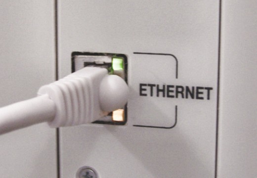
Ethernet cable connects a network interface card (NIC) with a hub or Ethernet switch. Ethernet cables can be purchased from a computer store. They come in two categories, flat and braided. The flat or solid cable is used when there is a need for a longer cable run. However, it is not flexible. Thus, its position is fixed. The braided cable is easier to use and is more flexible. However, it is useful only in places where a shorter cable run is needed. In the Ethernet cable pinout there are basically two cables: (1) the straight cable and (2) the crossover cable. The cables are color coded. It is very important to connect the cables properly because improperly connected cables can lead to loss of Internet connectivity. The straight cables can be used to make a crossover cable when needed.

What is Required for an Ethernet Cable Pinout?
- Category 5/5e or 6 braided or solid cable (decide according to use)
- RJ45 ends
- A crimper
- A wire cutter
The Straight Cable
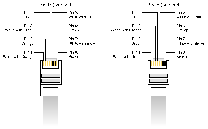
The straight cable is a through cable and it connects to the switch or hub. These cables function as the patch cords in an Ethernet connection. Both ends of these wires are the same. The TIA/EIA 568B has replaced the TIA/EIA 568A standard. However, both cable standards are still used as they are similar. Both standards use unshielded, twisted pair cables.
The Crossover Cable
The crossover cable formation can be used without a hub or switch. It is used in a peer-to-peer connection and when one needs to connect two Ethernet devices together without a hub or switch. It also connects two hubs to each other. The simplest way to achieve this is to use the 568 A at one end and the 568B at the other end of the RJ45 plug.
Color Coding the Wires
There are a total of eight wires inside the cable, twisted into four pairs. Each pair has a primary solid colored wire and another one with a primary white with a colored stripe running through its center. The stripe in the pair is of the same color as the solid color. The pinout for the cable 568A going from position one (that is, the wire that is attached to pin 1 of the RJ45 plug) is white/green, green, white/orange, blue, blue/white, orange, white/brown, brown, and for the 568 B is white/orange, orange, white/green, blue, white/blue, green, white/brown, and brown. The easiest way to remember how to wire a crossover cable is to switch the set of wires. That is, to switch the solid green and the solid orange and the white/green and the white/orange.
Related Articles on Ethernet Technology
- What is Ethernet?
- Understanding Ethernet
- Ethernet at the Data Link Layer
- Ethernet at Physical Layer
- Understanding Ethernet Networking
- Understanding Ethernet LAN Segmentation
- What is an Ethernet Card?
- What is an Ethernet Hub?
- What is an Ethernet Switch?
- Ethernet Cable
- Ethernet Cabling
- What Is the Ethernet Cable Pinout?
- What is a USB to Ethernet adapter?
- What is Power over Ethernet?
- What is an Ethernet crossover cable?
- Ethernet Cross Over Cable


Ali Hariri
I would like to see a step by step ethernet cable assembly. It is my first time connecting the blug to a cable. I have the tools, just need to see it in a picture.
memenode
How about videos? This video might help.