Ethernet is a media access method that is specified at the Data Link layer and uses specific Physical layer cabling and signalling techniques. It is important to be able to differentiate between the types of connectors that can be used to connect an Ethernet network together. I'll discuss the different unshielded twisted-pair cabling used today in an Ethernet LAN.
Network Cabling
It's important to understand the difference between the media access speeds Ethernet provides in computer cabling systems. However, it's also important to understand the connector requirements for each implementation before making any decision. The Electronic Industries Association and the newer Telecommunications Industry Association (EIA/TIA) is the standards body that creates the Physical layer specifications for Ethernet. The EIA/TIA specifies that Ethernet use a registered jack connector with a 4 5 wiring sequence on unshielded twisted-pair cabling (RJ-45).
The following points outline the computer network cabling requirements:
-
10Base2 50-ohm coaxial is also called thinnet which is up to 185 meters and supports 30 hosts per segment. Physical and logical bus is used with AUI connectors.
-
10Base5 50-ohm coaxial is also called thicknet which is up to 500 meters and supports 208 users per segment. It uses a physical and logical bus with AUI connectors. It is up to 2500 meters with repeaters and supports 1024 users for all segments.
-
10BaseT EIA/TIA category 3, 4, or 5, using two-pair unshielded twisted-pair (UTP) wiring supports one user per segment; up to 100 meters long.RJ-45 connector is used along with star topology.
-
100BaseTX EIA/TIA category 5, 6, or 7 UTP two-pair wiring supports one user per segment; up to 100 meters long. It uses an RJ-45 MII connector with a physical star topology and a logical bus.
-
100BaseFX Uses fiber cabling 62.5/125-micron multimode fiber supports point-to-point topology; up to 400 meters long. It uses an ST or SC connector, which are duplex media-interface connectors.
-
1000BaseCX Copper shielded twisted-pair that can only run up to 25 meters.
-
1000BaseT Category 5 is a four-pair UTP wiring that can run up to 100 meters.
-
1000BaseSX MMF using 62.5 and 50-micron core; uses a 780-nanometer laser and can go up to 260 meters.
-
1000BaseLX Single-mode fiber that uses a 9-micron core, 1300-nanometer laser and can go from 3 km up to 10 km.
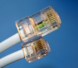
UTP Connections (RJ-45)
The RJ-45 connector is clear so you can see the eight wires mentioned with different colours that connect to the connector's pins. All of theses wires are twisted together into four pairs. Four wires carry the voltage and are considered tip. The other four wires are grounded and are called ring. The RJ-45 connector is crimped onto the end of the wire, and the pin locations of the connector are numbered from the left, 8 to 1.
Twisted wires inside UTP cable eliminate cross talk noise.. Unshielded cable can be used since digital signal protection comes from the twists in the wire. The more twists per inch, the farther the digital signal can supposedly travel without interference. For example, cat 5 cabling such as network cabling cat 5 and category 5 cabling UK have many more twists per inch than category 3 UTP does. Different types of wiring are used for building internetworks. You will need to use either a straight-through or crossover cable.
Straight-Through Cable
In a UTP implementation of a straight-through cable, the wires on both cable ends are in the same order. You can determine that the wiring is a straight-through cable by holding both ends of the UTP cable side by side and seeing that the order of the wires on both ends is identical.
You can use a straight-through cable for the following tasks:
-
Connecting a router to a hub or switch
-
Connecting a server to a hub or switch
-
Connecting workstations t a hub or switch
Crossover Cable
In the implementation of a crossover, the wires on each end of the cable are crossed.
It is used to transmit and receive for both rip and ring. Notice that pin 1 on one side connects to pin 3 on the other side, and pin 2 connects to pin 6 on the opposite end.
You can use a crossover cable for the following tasks:
-
Connecting uplinks between switches
-
Connecting hubs to switches
-
Connecting a hub to another hub
-
Connecting a router interface to another router interface
-
Connecting two PCs together without a hub or switch
When trying to determine the type of cable needed for a port, look at the port and see if it is marked with an "X." by using a straight-through cable when only one port is selected with an "X." and use a crossover when neither port has an "X." or when both ports are designated with an "X"
Rolled Over Cable
In the implementation of a rollover cable, the wires on each end of the cable are opposite. It broadcast to receive and receive to transmit on both side, for both tip and ring. Notice that pin 1 on one side connects to pin 8 on the other side, pin 2 connects to pin 7 on the opposite end, pin 3 connects to pin 6 on the opposite end and pin 4 connects to pin 5 on the opposite end.
You can use a rolled cable for the following tasks:
-
For out of band console connection between the console port (RJ45) of the manageable switches and the com port (DB9) of the computer using a RJ45 to DB9 terminal.
-
For out of band console connection between the console port (RJ45) of manageable routers and the com port (DB9) of the computer using a RJ45 to DB9 terminal.
Follow Us!