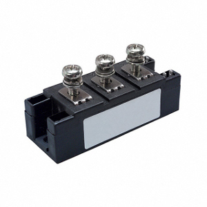
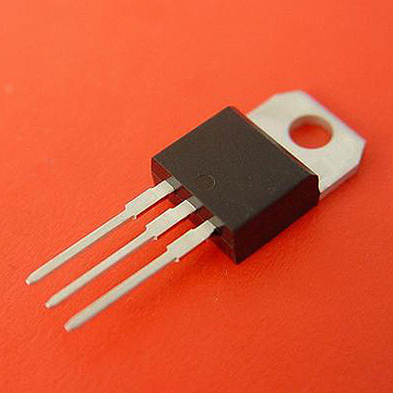
A thyristor is a solid state semiconductor device that consists of four alternating layers of N-type and P-type material. Many sources consider thyristors to be the same as Silicon Controlled Rectifiers (SCRs). In some cases they are defined as a large group of devices – the eligibility criterion being that the device should consist of a minimum of 4 layers of alternating N and P-type material. A thyristor functions as a bistable switch, which means that it starts conducting when its gate receives a pulse of current. It conducts until the voltage in the device reverses, i.e., until it is in the forward biased state. Thyristors only turn off when the forward current drops to zero.
Types of thyristors include:

- Silicon Controlled Rectifier (SCR)
- Gate Turn-off Thyristor (GTO)
- Triode AC switch (TRIAC)
- Static Induction Transistor/Thyristor (SIT/SITh)
- MOS Controlled Thyristor (MCT)
- Distributed Buffer – Gate Turn-off Thyristor (DB-GTO)
- Integrated Gate Commutated Thyristor (IGCT)
- MOS composite Static Induction Thyristor/CSMT
- Reverse Conducting Thyristor (RCT)
History
William Shockley brought forth the concept of Silicon Controlled Rectifier (SCR) in 1950. He received support from Moll and other engineers at Bell Labs. Following this, power engineers from General Electric (G.E.) who were under Gordon Hall’s guidance, created the SCR in 1956. Commercial production followed soon after, and was made possible due to the efforts of G.E.’s Frank W. “Bill” Gutzwiller.
How does a Thyristor Function?
A thyristor is a three terminal semiconducting device, consisting of four alternating layers of N-type and P-type materials. An example of an arrangement is P-N-P-N. The thyristor’s main terminals, which are referred to as cathode and anode, are spread across all the four layers. The gate, which is the thyristor’s control terminal, is attached only to the P-type material situated near the cathode. There is also a variant known as the Silicon Controlled Switch (SCS) that connects all four layers to the terminals.
Thyristors are most commonly used in Alternating Current (AC) circuits, where the forward current drops to zero during each cycle, ensuring that it turn off every time. However, this also means that the gate needs to be activated during each cycle to turn it back on. The timing of these two functions enables thyristors to effectively function as power controllers. By turning on the thyristor at the beginning of an AC voltage supply’s positive voltage excursion, its forward conducting is at the longest duration, resulting in maximum power delivery. Conversely, when the thyristor is turned on at the end of the positive excursion, the conduction time is at the shortest duration, resulting in minimum power delivery. As effective as thyristors are in an Alternating Current environment, they are quite useless when used with Direct Current (DC) where there is no polarity reversal, except in a few safety protection applications.
A thyristor’s function can be divided into three states:
1.Reverse Blocking mode – The voltage is applied in a direction that a diode will obstruct.
2.Forward Blocking mode – The voltage is applied in the direction that the diode will conduct, but the thyristor awaits a trigger to begin conducting.
3.Forward Conducting mode – The thyristor is now triggered to conduct, and continues to conduct until the forward current drops lower than a threshold value referred to as Holding Current.
Gate Terminal
The thyristor’s three P-N junctions are named serially from the anode as J1, J2, and J3. When the anode is at a positive potential (VAK) with respect to the cathode and no voltage is applied at the gate, J1 and J3 are in the forward bias mode, while J2 is in reverse bias which stops conduction. This is the OFF state. In the case where VAK is increased beyond the breakdown voltage VBO of the thyristor, the thyristor starts to conduct due to the avalanche breakdown of junction J2. This is the ON state.
When a positive potential VG is being applied at the gate terminal with respect to the cathode, the junction J2 breaks down at a lower value of VAK. Hence, the thyristor can be brought to the ON state by choosing the right value of VG.
After the avalanche breakdown, the thyristor will continue to conduct, no matter what the gate voltage is, until:
1.the potential VG is taken away and
2.the current passing through the device from the anode to the cathode is less than the holding current
Therefore, VG can be a voltage pulse, which can be characterized in terms of two factors: gate trigger voltage (VGT) and gate trigger current (IGT). The variation in gate trigger current is inversely proportional to gate pulse width, in a way that makes it clear that a minimum gate charge is needed to trigger the thyristor.
Applications
Thyristors are mostly used with alternating currents where the polarity change causes the device to switch off automatically. This operation is known as Zero Cross. They are used as controllers that phase angles, better known as phase fired controllers, trigger. In digital circuit power supply, they play the role of circuit breakers and prevent damage to system components if there is a power failure. In such systems, thyristors have a zener diode attached to their gates. When the voltage increases beyond the zener voltage, it causes the thyristor to conduct and break the circuit, acting as an upstream fuse.
Thyristors were commercialized in the early 1970s in devices that stabilized the power supply in color televisions. These became totally unpopular with AC power suppliers, as the simultaneous switching of multiple televisions around the same time led to asymmetry in the power supply waveform. This forced DC back into the grid, which lead to transformer core saturation and overheating. As a result, thyristors were soon phased out from this kind of usage.


jerah
drawing of the three states of thyristor.