In the past, two main termination specifications were used. One was for UTP data cable infrastructure and the other for phone cable infrastructure. Today, structured cable systems are in use. 568A is one such standard. 568A is a standard for the pin arrangements of RJ-45 connectors on Unshielded Twisted Pair (UTP) wire. The cryptic number 568 refers to the order in which the individual wires inside a CAT 5 cable are terminated. The 568 standards were actually developed by the TIA (Telecommunications Industry Association) and the EIA (Electronics Industry Association) in America to reduce confusion in their industry. These were then adopted by other standards organizations around the world.
Two wire color-code standards apply: EIA/TIA 568A and EIA/TIA 568B. The standards are technically the same and operate in the same manner. The only difference between the two schema's is that the green and orange pins are terminated to different pins as shown below. There is no difference in signal. Both the 568A and 568B are used as patch cords for Ethernet connections.
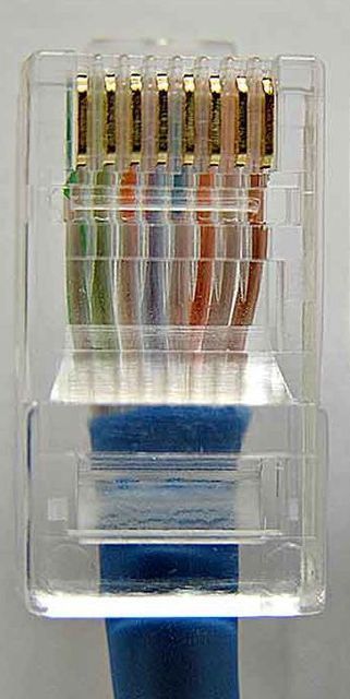
568A Color Codes
When you buy a roll of cable, it does not come with jacks at the ends. You will need to cut off the amount you need and then order the pairs of wires according to the type of cable you want and then crimp them to an RJ-45 jack so that the cable may be usable. The table below shows the order in which you connect the wire pairs to an RJ-45 jack. Pin numbers are read left-to-right with the connector tab facing down. This standard is more common in jumpers and in new network installations.
|
Pin (Jack) |
Pin (Plug) |
Color |
Pair |
|
1 |
8 |
White/Green |
3 – Tip |
|
2 |
7 |
Green |
3 – Ring |
|
3 |
6 |
White/Orange |
2 – Tip |
|
4 |
5 |
Blue |
1 – Ring |
|
5 |
4 |
White/Blue |
1 – Tip |
|
6 |
3 |
Orange |
2 – Ring |
|
7 |
2 |
White Brown |
4 – Tip |
|
8 |
1 |
Brown |
4- Ring |
NB- When it says White/Orange or White/Green etc, know that the wire is white with an orange strip or white with a green strip etc.
568B Color Codes
The table below shows the order in which you connect the wire pairs to an RJ-45 jack for 568B. This standard is more common for installed wiring and has been used previously on most off the shelf Ethernet cables.
|
Pin (Jack) |
Pin (Plug) |
Color |
Pair |
|
1 |
8 |
White/Orange |
2 – Tip |
|
2 |
7 |
Orange |
2 – Ring |
|
3 |
6 |
White/ Green |
3 – Tip |
|
4 |
5 |
Blue |
1 – Ring |
|
5 |
4 |
White/Blue |
1 – Tip |
|
6 |
3 |
Green |
3 – Ring |
|
7 |
2 |
White Brown |
4 – Tip |
|
8 |
1 |
Brown |
4- Ring |
In order to wire a crossover Ethernet cable, you will need to use both the 568A and 568B standards. Wire one end with 568A and the other end with 568B. This simply means that you switch the green set of wires with the orange set of wires. Specifically, switch the solid Green (G) with the solid Orange, and switch the green/white with the orange/white. Once the preferred schema has been selected, it should be maintained throughout design and installation. This ensures that errors are avoided during maintenance.
Follow Us!