A routing table is a grouping of information stored on a networked computer or network router that includes a list of routes to various network destinations. The data is normally stored in a database table and in more advanced configurations includes performance metrics associated with the routes stored in the table. Additional information stored in the table will include the network topology closest to the router. Although a routing table is routinely updated by network routing protocols, static entries can be made through manual action on the part of a network administrator.
How Does a Routing Table Work?
Routing tables work similar to how the post office delivers mail. When a network node on the Internet or a local network needs to send information to another node, it first requires a general idea of where to send the information. If the destination node or address is not connected directly to the network node, then the information has to be sent via other network nodes. In order to save resources, most local area network nodes will not maintain a complex routing table. Instead, they will send IP packets of information to a local network gateway. The gateway maintains the primary routing table for the network and will send the data packet to the desired location. In order to maintain a record of how to route information, the gateway will use a routing table that keeps track of the appropriate destination for outgoing data packets.
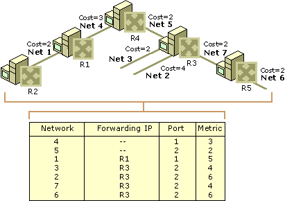
All routing tables maintain routing table lists for the reachable destinations from the router’s location. This includes the address of the next networked device on the network path to the destination address which is also called the “next hop.” By maintaining accurate and consistent information regarding network nodes, sending a data packet along the shortest route to the destination address on the Internet normally suffices for delivering network traffic and is one of the baseline characteristics of the OSI network and IP network layers of network theory.
What is the Primary Function of a Network Router?
A network router’s primary function is to forward data packets to the destination network included in the destination IP address of the outgoing data packet. In order to determine the appropriate destination of the data packet, the router conducts a search of the destination addresses stored in the routing table The routing table is stored in RAM on the gateway router of the network and includes information about destination networks and the “next hop” associations for those address. This information helps the router both determine and identify the best outgoing location for the data packet to be sent to find the ultimate network destination. This location may also be the gateway interface of any directly connected networks.
What is a Directly Connected Network?
Directly connected networks are attached to one of the router interfaces of a local network. Since the router interface is normally configured with both a subnet mask and an IP address, the interface is also considered to be a network host on the attached network. As a result, both the subnet mask and network address of the interface are entered into the locally stored routing table (along with the interface type and number). The entry is made as an attached network. A common example of a directly connected network are web servers that are on the same network as the computer host and constitute a directly connected network in the routing table stored on the gateway or router.
What is a Remote Network?
Remote networks are not directly connected to the gateway or router on the network. As far as a routing table is concerned, a remote network is only able to be reached by forwarding data packets to other routers. These networks are added to the local routing table through the configuration of static network routes or by use of a dynamic routing protocol. Dynamic routes are “learned” by the router by tracking the most efficient means of delivering data packets making use of a dynamic routing protocol. Network administrators will typically be the only individuals authorized to manually configured static routes to remote network destinations.
What are Some Problems with Routing Tables?
One of the most significant challenges with modern routing tables is the vast amount of storage required to store the information required to connect a large number of networked computing devices on limited storage on the router. The current technology used on most network routers for address aggregation is the Class Inter-Domain Routing (CIDR) technology. CIDR makes use of a bitwise prefix matching scheme. This scheme relies on the fact that each note in a network will have a valid routing table which is consistent and will avoid loops. Unfortunately, in the currently employed “Hop/Hop” routing model, the tables are not consistent and loops do develop. This results in data packets finding themselves in a never-ending lop and has been a major problem for network routing for years.
What are the Contents of a Routing Table?
Although each network routing table can contain different information, the primary fields of every table include: the network ID, cost or metric, and the next hop.
Network ID – This field in a routing table will include the destination address subnet.
Cost or Metric – This field will save the metric or “cost” of the network path that the outgoing data packet will be sent.
Next Hop – The gateway or next hop is the destination address of the next network location that data packets will be transmitted to on their way to the destination IP address.
Additional information that can be found in a network routing table includes:
Network Route Quality of Service – Over time, some network routers are designed to store a quality of service metric associated with different network routes stored in routing tables. One of these metrics simply indicates that a given route is operational and sets a flag in the table in order to save memory.
Filtering Criteria or Access Lists – This entry will hold information or links to information that has the latest information regarding access lists or various filtering criteria that may be associated with a given network route.
Network Interface Information – This can represent data regarding specific Ethernet cards or other information that can be used for optimizing the routing of network data packets.
What is a Forwarding Table?
A network forwarding table, or forwarding information base (FIB) is normally used when bridging networks or conducting various routing operations in order to help locate the correct interface that an input interface to the network should send a data packet.
Applications of Forwarding Tables at the Data Link Layer
Forwarding tables have found some use at the data link layer. For example, MAC (media access control) protocols on local networks have an address that is not significant outside of this medium and can be stored for use in a forwarding table to help with Ethernet bridging. Other uses include ATM (Asynchronous Transfer Mode) switches, frame relays, and MPLS (multiprotocol label switching). For use with ATM, there are both data link layer local addresses and others that have a fair amount of significance for use on the network.
How are Forwarding Tables used with Bridging?
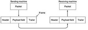
When a MAC layer bridge identifies the interface that a source address was first seen, the association with the interface and address is made. As a result, when there is a frame received at the bridge a destination address located in the respective forwarding table, the frame will be transmitted to the interface that has been stored in the FIB. If the address has not previously been seen, it will be treated as a “broadcast” and will send the information out on all of the active interfaces with the exception of the one that received the information.
How Does a Frame Relay Work?
Although there is not a centrally defined method or process that determines how a forwarding table or frame relay works, the typical model found throughout industry is that a frame relay switch will have one statically defined forwarding table per interface. Once a frame along with a DLCI (data link connection identifier) is received on a given interface, the table that is associated with the interface will provide the outgoing interface. This also provides the new DLCI to insert into the frame address field in the table.
How Do ATM Forwarding Tables Work?
An ATM switch contains a link-level forwarding table similar to the model used in a frame relay table. Instead of using DLCI; however, the interface includes forwarding tables which include the virtual path identifier, the outgoing interface, and the virtual circuit identifier. The table can either be distributed by the PNNI (private network to network interface) protocol or statically defined. When the table is created by PNNI, the ATM switches that are located on the edge of the network or the cloud and will map the end-to-end identifiers in the network to identify the next hop VCI or VPI.
What is Multiprotocol Label Switching (MPLS)?
Multiprotocol Label Switching (MPLS) has a number of aspects that are similar to ATM. MPSL uses LER (label edge routers) that are located on the boundaries of the MPSL cloud map located between a link local label and the end-to-end identifier (which can be an IP address). At every hop in MPLS, a forwarding table is used to tell the LSR which outgoing interface should receive the packet. It also determines what label to apply when forwarding the packet to that interface.
What are the Applications of Forwarding Tables at the Network Layer?
Unlike network routing tables, a forwarding table or FIB is optimized to quickly lookup a destination address for information. Earlier versions of forwarding tables would cache a subset of the total number of routers that were most frequently used for forwarding data packets. Although this methodology worked for Enterprise-level routing, when employed for access to the entire Internet, significant performance hits resulted from having to constantly refresh the relatively small cache. As a result, forwarding table implementations started to shift methodology to ensuring a FIB had a corresponding RIB which would be optimized and updated with a full set of routes that the network router had learned. Additional improvements made to FIBs include faster hardware lookup capabilities and TCAM (ternary content addressable memory). Due to the high cost of TCAM; however, this technology is normally found on edge routers.
How Do Forwarding Tables Help Defend against Denial of Service Attacks?
Over time, using a forwarding table (or FIB) to help filter inbound data packets has become an Internet “best practice” to help defend against Denial of Service (DoS) attacks on a network. In the most basic form, ingress filtering will use an access list to determine who to drop packets from and mitigate the damage that a DoS attack will achieve. If the network has a larger number of adjacent network, then the use of the access list method can quickly become performance impacting on the router. Other implementations will have the address lookup the source address in the FIB. IF there is not saved route to the source address of the information, the algorithm assumes the packet is from a spoofed or false source address and is discarded as possibly being part of a DoS attack.
How Forwarding Tables are Used for Quality of Service Assurance?
FIB tables can be used in a number of network management schemes to help ensure a higher quality of service for certain data packets on the network. This differentiation can be based on a field int eh data packet that indicates the routing priority of the packet in addition to how long the packet desires to remain “alive” in the event of network congestion. When routers support this type of service, they are typically required to send the data packet to the network interface which “best” matches the service requirements of the data normally called DSCP (differentiated service code points). Although this act slightly increases the overall computing power required to process the packet, the act is not considered significantly impacting on network resources.


sangam
i wanted to know if we could invoke the command prompt in java coding?
if there is any way please help me
Sphumelele Cele
Hey there
I am confuse and would like to ask the achitercture of a routing table. As in static routing the routing information is manually entered by Administrator I reckon it is sitable for small network and dynmic for larger network.
Thanks
sangam
hi sphumellele the router main part is the buffer and the routing table
the buffer stores the data which u want to send and the routing table acts as a intelligent table which chooses the best path to send your data to the required destination.