When routers need to forward packets, they interpret the packets’ addresses then use the information in the routing tables to pass the packet on. Data packets contain both source and destination addresses in their packet headers. This is the information that is used when routing decisions need to be made.
The destination address is compared with the local address to determine the following information on how to route the packet:
- Should the packet be sent up the stack on the local host?
- Should the packet be sent to a different destination?
- Should the packet simply be ignored?
The routing table contains route entries. The different types of routes in the routing are:
- Host route: A host route provides a route to either of the following destinations:
- Specific destination host
- Broadcast address
Host routes are identified in the routing table by a network mask of 255.255.255.255.
- Network route: A network route provides a route to the following destination:
- Specific destination network
Network routes are identified in the routing table by a subnet mask between 0.0.0.0 and 255.255.255.255.
- Default route: Each routing table includes one default route. When a packet is received that has a destination address that does not correspond to any address in the routing table, the default route is used to forward this packet. The default route is identified in the routing table by a 0.0.0.0 address and a 0.0.0.0 network mask.
Users can view the IP routing table’s content from:
- Routing and Remote Access management console
- Click Start, Administrative Tools, and click Routing and Remote Access to open the Routing and Remote Access console.
- In the console tree, expand the IP Routing node.
- Right-click the Static Routes node, then select Show IP Routing Table from the shortcut menu.
- The entries in the routing table are displayed in the right pane of the Routing and Remote Access console.
- Command line
- Open a command line window
- Enter
route print
With static routing, administrators have to manually create and modify the routing table entries. Each time a change occurs in the network configuration, the entries in the routing table have to be modified to reflect these changes. Static routing works well in a small network where it is easier to configure a small number of static routes than it is to configure dynamic routing.
With dynamic routing, routing protocols enable IP routers to communicate with each other. The routing protocols also enable routers to share the information they have in their routing tables. A router that is configured to use dynamic routing forwards its routing table’s content to the other routers configured for dynamic routing at regular time periods or intervals.
Understanding the Windows 2000 and Windows XP Routing Tables
The Windows 2000 and Windows XP routing table can however only be accessed from a command line. The Routing and Remote Access management console cannot be used to view the contents of a Windows 2000 routing table and Windows XP routing table.
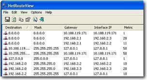
The standard fields in a Windows 2000 routing table and Windows XP routing table are:
- Network Destination: The Network Destination field contains entries that the router compares to each packet’s destination address that it receives. Some of these entries, like the default route entry, are the same for most routing tables.
The network ID for the route can be either of the following:- IP address for a host
- Subnet address
- Supernet address
- Class-based address
- Netmask: This is the ask used to associate the destination address with the network destination. The Netmask value basically specifies what element of the destination address of the packet is matched to the Network Destination entries. The largest match determines the route that will be applied to a specific IP packet.
- Gateway: After a route is applied to an IP packet, the value specified in the Gateway field defines the forwarding or next-hop IP address that the packet will use for the network destination.
- Interface: The value of the Interface field defines the IP address of the network interface card (NIC) used to forward the packet to the next hop.
- Metric: The value in the Metric field indicates the cost of using the route. The metric determines which route is applied among the different route options.
The additional fields that can be present in the Windows 2000 routing table and Windows XP routing table are:
- Directly Attached Network ID Routes: This information is used for all routes that are directly attached. In this case, the Gateway IP address is the interface’s IP address on the specific network for all networks that are attached.
- Remote Network ID Routes: This information is used for those routes that are available through other routers. The routes are therefore not directly available. Here, the Gateway IP address is the local router’s IP address that is located between the forwarding node and the remote network.
- Host Routes: This field allows users to enter a route to a specific destination host. In this case, the network destination is the specific host’s IP address. The subnet mask is 255.255.255.255.
- Default Route: Users can enter a default route that will be used to forward packets where the network ID or host route cannot be found in the routing table. In this case, the network destination is 0.0.0.0. The subnet mask is 0.0.0.0.
How to view a Windows 2000 routing table or Windows XP routing table:
- Click Start, Run, enter cmd, then press Enter to open a command prompt window.
- Enter the command
route helpto display the different commands that can be used with theroutecommand. Press Enter. - To view the routing table, enter
route print. - The default routing table entries are created whenever the TCP/IP protocol starts on the specific computer.
- The default route should be displayed as 0.0.0.0 with the subnet mask of 0.0.0.0.
- The loopback route should be displayed as 127.0.0.0 with a subnet mask of 255.0.0.0 and gateway 127.0.0.1.
- The Network Destination column should contain a route entry for the local computer.
- Enter
exitto close the command prompt window.
How to add routing table entries with the route command:
- Click Start, Run, enter cmd, then press Enter to open a command prompt window.
- Enter the command
route helpto display the different commands that can be used with theroutecommand. Press Enter. - The command line format used to add a routing table entry is:
route add [destination] [mask] [gateway] [metric] IF [interface]
- To verify that the correct routing table entry was added, enter route print to view the routing table.
- If the incorrect gateway or metric was entered, use the route change command to modify these values.
- If any other information was incorrectly entered, use the
route deletecommand to delete the specific entry and theroute addcommand to re-enter the routing table entry.
How to delete routing table entries:
- Click Start, Run, enter cmd, and press Enter to open a command prompt window.
- The command line format to delete a routing table entry is:
route delete [destination]/code>
- To verify that the correct routing table entry was deleted, enter
route printto view the routing table.
Understanding the Windows Server 2003 Routing Table
The Windows Server 2003 routing table contains the following standard fields:
- Network Destination
- Netmask
- Gateway
- Interface
- Metric
- Protocol
With Windows Server 2003, view the routing table using:
- The
routecommand from the command line. Theroutecommands in Windows 2000, Windows XP, and Windows Server 2003 are all the same. - The Routing and Remote Access management console. Access the Routing and Remote Access console by clicking Start, Administrative Tools, and Routing and Remote Access.
The main differences between the previous routing tables and the Windows Server 2003 routing tables are listed below:
- With Windows Server 2003, the routing metric is automatically calculated by the TCP/IP protocol. The interface’s speed determines the routing metric. The feature is automatically enabled by default.
- With the previous routing tables, the netmask for the Class D multi-cast is specified as 224.0.0.0. With Windows Server 2003 routing tables, the netmask for the Class D multi-cast is specified as 240.0.0.0.
- The routing tables in Windows Server 2003 can be viewed and maintained through the Routing and Remote Access management console. In Windows 2000 and Windows XP, routing tables can only be viewed and modified from the command line with the
routecommand.
How to view the routing table in Window Server 2003:
- Click Start, Administrative Tools, and Routing and Remote Access to open the Routing and Remote Access console.
- In the console tree, expand the IP Routing node.
- Right-click the Static Routes node and select the Show IP Routing Table command from the shortcut menu.
- When the routing table is viewed from the Routing and Remote Access console, the Protocol field is displayed. The Protocol field indicates the manner in which the route was discovered.
How to add routing table entries with the Routing and Remote Access console:
- Click Start, Administrative Tools, and Routing and Remote Access to open the Routing and Remote Access console.
- In the console tree, expand the IP Routing node.
- To view the routing table for an interface, right-click the specific interface then select Show IP routing Table from the shortcut menu.
- To add a static routing table entry, expand the IP Routing node then select Static Routes.
- Right click Static Routes and click Add Static Route on the shortcut menu.
- The Static Route dialog box opens.
- From the Interface drop-down list box, select the interface.
- Enter a value for Destination.
- Enter a value for Network mask.
- Enter a value for Gateway.
- Enter a value for Metric.
- Leave the demand-dial connections check-box enabled if the route is to be used for demand-dial connections.
- Click OK.
How to Delete Routing Table Entries with the Routing and Remote Access Console
- Click Start, Administrative Tools, and Routing and Remote Access to open the Routing and Remote Access console.
- In the console tree, expand the IP Routing node.
- Select Static Routes to display the current static routes in the right pane.
- Locate and select the static route to be removed from the IP routing table.
- Right-click the specific static route then select Delete from the shortcut menu.
- The static route is immediately removed from the routing table.
How to disable the automatic metric calculation feature:
- Click Start, Control Panel, and Network Connections.
Select Local Area Connection. - The Local Area Connection Properties dialog box opens.
- In the This connection uses the following items box, select the Internet Protocol (TCP/IP). Click Properties.
- When the Internet Protocol (TCP/IP) Properties dialog box opens, click Advanced.
- The Advanced TCP/IP Settings dialog box contains a number of tabs: IP Settings tab, DNS tab, WINS tab, and Options tab.
- The IP Settings tab is divided into the following areas:
- IP addresses
- Default gateways
- Automatic metric
- In the Automatic metric area of the IP Settings tab, uncheck the Automatic metric check-box to disable the automatic metric calculation feature.
- Manually enter the Interface metric once the automatic metric calculation feature is disabled.
- Set the value for the Interface metric in the available field.
- Click OK to save the changes and close the Advanced TCP/IP Settings dialog box.
- Click OK to close the Internet Protocol (TCP/IP) Properties dialog box.
- Click OK to close the Local Area Connection Properties dialog box.

windows support
just what I needed thanks…
ks
Hi, thanks for article.. can you please explain..how to check Add & Delete history in route table?
Cyber Learning
Hello
I saw your article and am hoping to get some help.
I have a 4-port/wireless router (VPN-enabled) set-up in the office.
3 PCs (Windows 7 Pro) are connected to a router (wired connection).
1 VOIP adapter is connected to a router (wired connection).
1 PC (Windows XP Pro SP3) is connected to a router (wireless connection).
When I am on the field, I need to access to these devices over VPN. I can access to 3 PCs (wired connection to router) over VPN.
However, I cannot connect to a PC (wireless connection to router) over VPN.
Would you please advise me how I can access to this PC (wireless connection to router) over VPN?
With best regards,