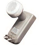
An LNB (Low Noise Block aka LNC- Low Noise Converter) is used for communications (broadcast) satellite reception. The LNB is usually affixed either in or on the satellite dish.
The LNB’s purpose is to utilize the super heterodyne effect and amplify and convert a wide block (band) of frequencies. This helps compensate the signal loss associated with typical coaxial cable at relatively high frequencies.
The term ‘low noise’ relates to the quality of the 1st stage input amplifier transistor, measured in either called Noise Temperature units, Noise Figure units, or Noise Factor units.
Both Noise Factor and Noise Figure are easily converted into Noise Temperature units. A lower Noise Temperature rating is always better (i.e. an LNB with a Noise Temperature of 100K is 2x as good as one rated 200K).
The term ‘Block’ refers to the conversion of a higher block of microwave frequencies (received from the satellite- typically in the range 4 GHz to 21 GHz) being down converted to a lower block range of frequencies for the receiver.
The “low-noise” part also indicates that amplification and mixing takes place prior to cable attenuation in a circuit that requires no power supply or receiver.
With the high frequencies that satellites operate at, it is critical that the noise is controlled prior to signal processing.
An LNB helps keep the overall sound and picture of satellite TV from becoming greatly degraded, without the need for introducing a much larger dish reflector.
For wide band satellite television carrier reception (generally 27 MHz wide band), the tolerance (accuracy) of the LNB local oscillator frequency needs to be in the range of ±500kHz. This makes low cost DROs (dielectric oscillators) feasible.
However, for reception of narrow bandwidth carriers (i.e. 16-QAM), a highly stable, low phase noise dedicated LNB (local) oscillator is required.
They typically contain an internal crystal oscillator (or 10 MHz reference from the indoor unit) and a PLL (Phase-Locked Loop) oscillator, and naturally tend to be more expensive.
LNB Feedhorns (LNBFs)
DBS (Direct Broadcast Satellite) dishes use an LNBF, which matches the antenna’s feedhorn up with the LNB.
Often times, small diplexers are utilized to distribute the resulting IF signal (typically in the 950 MHz to 1450 MHz range) and “piggyback” these signals with same TV cable that carries lower-frequency (terrestrial) television signals from a typical outdoor (terrestrial) antenna.
The TV set receiver also has another diplexer that separates the signals.
Universal LNBs
A universal LNB can receive both polarizations and the full range of frequencies in both the Ku and C satellite band.
Some LNBs can receive both polarizations simultaneously (through 2 different connectors), while other LNBs have either switchable or adjustable polarization.
Typical Universal LNB specifications are:
- Local Oscillator (LO): 9.75 GHz /10.6 GHz
- Frequency: 10.7 GHz-12.75 GHz
- Noise Figure (NF): 0.7 dB
- Polarization: Linear
Standard DBS LNB example:
- Local Oscillator (LO): 11.25 GHz
- Frequency: 12.2 GHz-12.7 GHz
- Noise Figure (NF): 0.7 dB
- Polarization: Circular
Typical North American C-band LNB specs:
- Local Oscillator (LO): 5.15 GHz
- Frequency: 3.6-4.2 GHz
- Noise Figure (NF): 15 to 100 Kelvins (uses Kelvin ratings as opposed to dB rating)
- Polarization: Linear
Dual and Quad LNBs are multiple LNBs in one package that allow for multiple receivers (on one dish).
A Dual LNB consists of 2 universal LNBs (affixed at a small offset angle in a single housing) and uses only one “F” connector and coaxial cable connection to the converter box.
Though also a Dual LNB system, the Monobloc LNB has only one output and only one (satellite) transmission as compared to dish systems that have two or more separate LNBs. Each LNB is connected to separate receivers in which both transmissions can be simultaneously viewed or recorded.
The Monobloc LNB was specifically designed to receive signals from satellites that are spaced very close together. For example, parts of Europe use a Monobloc LNB to receive the Astra 1 (19E) and Hotbird (13E) satellites, eliminating the need for an expensive rotator.
Quad Universal LNB (a.k.a. Quad-Output LNB)
The Quad Universal LNB can accommodate four separate receivers, as each receiver has independent control of band and polarization via 13v. and 17v. and 22kHz on/off switching respectively.
This LNB is primarily deployed in the Sky Digiboxes (with 2 LNB inputs and internal hard disks for recording one program while the user watches another).
Two LNB outputs would go to one “Sky Plus” Digibox, leaving the other 2 LNB outputs for either 2 standard Digiboxes or to one additional Sky Plus Digibox.
OCTO LNBs
An OCTO LNB is the same as above, except that it has 8 independent outputs.
Quattro Universal LNB’s
This is a 4-output LNB, specifically designed for use as a “head end” I.F. distribution system (for apartment complexes). LNBs can generally supply (up to) 16 outputs for separate dwellings or Digiboxes. The 4 outputs of the Quattro Universal LNB are:
- Low band horizontal polarization
- High band horizontal polarization
- Low band vertical polarization
- High band vertical polarization
As a general rule of thumb, any standard (universal) LNB will work with any circular (prime focus) dish or offset focus dish. Though actually taller than it is wide, an offset focus dish appears circular as far as the LNB is concerned.
However, dishes that are wider than they are tall require a special LNB.
LNBs that are used for satellite TV reception contain DROs (dielectric resonator stabilized local oscillators), which are a ‘pellet’ of material that resonates at the required frequency.
A DRO is relatively unstable compared to a quartz crystal resonator or oscillator.
Tolerances vary by as much as +/- 250 kHz to 2 MHz (Ku band), which include the extremes of the full operating range.
Because most TV carriers are quite bandwidth wide (i.e. 27 MHz band) even a 2 MHz error can successfully be received.
Though PLL LNBs are typically more expensive, the advantage of deploying an external reference PLL LNB is that constant temperature stability is much easier to maintain.
LNB Supply Power
The DC supply (typically in the 13v. to 19v. range) is cable line fed to the LNB and it is often times possible to alter the polarization by changing this voltage.
Alteration via the frequency band is also possible, albeit less common. Efficiently weather proofing the outdoor connector is critical, as oxidation and corrosion occur rapidly. This, in turn, directly relates to signal degradation.
Both the outer and inner conductors must make solid electrical contact.
High resistance causes the LNB to switch permanently into the low voltage state over time, and leads to overall signal deterioration.
If physically trouble shooting a system, be aware that the electrical antenna contacts between the BUC chassis and LNB are often times difficult to navigate and ‘earth loop’ currents may also propose a problem.
As a matter of fact, it is entirely possible to become severely shocked in discovering 50 Hz or 60 Hz AC Mains currents on the outer conductors. Be extremely cautious.
The quality and smoothing of the DC supplies used for the LNBs are also of great importance.
Testing an LNB
- Check the ammeter drawing the DC current from the power supply (approx. number of mA’s provided by the manufacturer).
- Poor quality (or corroded) F type connections are the most typical cause of concern.
- The center pin (of the F connector plug) should stick out ~ 2mm, away from the surrounding ring.
- A satellite finder power meter is also helpful. By pointing the LNB up at outer space (clear sky), the noise temperature contribution from the surroundings becomes negligible.
The meter reading will directly correspond to the LNB’s noise temperature.
If, for example, pointing the meter to outer space reads 100K (K is short for Kelvin, which measures absolute temperature), then the user points the LNB towards the ground (say at a temperature of approximately 300K), the noise power meter reading should go up accordingly, to roughly 400K (100K +300K).
LNBs that fail on a particular polarization (or particular frequency band) may only do so at certain temperatures.
If attempting to replace an LNB in a VSAT system, be sure to check both the supply voltage and the transmit reject filter as continuously blowing up LNBs can get cost prohibitive quite rapidly.
Overloading an LNB
If the user has a very large dish (i.e. ~7m diameter), and it is aimed at a satellite with signals intended for small dish antennas (i.e. ~70cm diameter), the overall 20 dB increase in signal strength (being fed into the LNB) may be ample enough to overload some of the internal transistor amplifier stages.
Because this is not always obvious, it is wise to measure the LNB’s composite output power (using a power meter) and compare this with the 1 dB compression point that the manufacturer supplies.
Alternatively, users can do an antenna pattern test (on both a high power and a low power satellite). Any non linearity problem (with the high power satellite) will become clearly discernible.
To overcome this problem, users may need to invest in a special LNB (low gain or high power output level) if they have a large dish.
The “poor man’s” field expedient means of fully testing an LNB is to hook it up to the desired dish (aligning the dish and LNB) and connect it to a satellite receiver.
Note the time of day and standard thermometer temperature and check to see if each channel is there.
If all channels are present, take note and wait until there is a temperature variance of ~40 to 50 degrees higher or lower (Fahrenheit) and perform the exact same test again.
If it continues to work through a net temperature swing of at least 40 degrees, then the LNB should work for at least a while.
Keep in mind, however, that the reverse is not necessarily true. Missing channels can also be due to a cable, receiver, or dish (due to distortion, warpage, or misalignment) fault.
A process of elimination (by swapping the dish, the cable, and the receiver) and bearing in mind that not all receivers work correctly with all LNBs will go a long way in aiding troubleshooting endeavors.
Also, bear in mind that while a cheap satellite finder meter gives the average strength of all frequencies and an expensive satellite finder meter can target specific frequencies, neither will indicate whether frequencies are missing.
Lastly, most testers and meters draw off of low amperage battery power. If the battery cannot supply enough current to the LNB, it will ultimately give a false reading.
SADIQ BENJAMIN
Why do we cover LNB after installation?
DJ
help…..rg6q coax run in about 185 feet from receiver to direct tv dish….I only get a signal on the odd numbered transponders….zero on all even numbered transponders. I figure that the voltage drop over that cable length is the problem….what do I do to get the voltage up where is should be….13 and 18?
Garry DIck
I have a tester and it shows that I am picking up signal but get no reception on the TV could this be a poor LNB
computerfreak
I heard high-grade ratio signal detectors are cooled with liquid nitrogen or even helium. Does ambient temperature affect LNB performance likewise?
Alick Gombanila
Please ,I want to know what kind of device should I use to convert the signals from the digibox receiver to TV searchable signals for RF ,such that I can distribute the signals to all of my house rooms,please help me.
sohrab khan
hi all ,
i have some confusion , why the LNB position is 90 degree change in central feed and offset….mean in offset antenna LNB position and central LNB position is 90 degree change…plz help
Mike Casady
My station is trying to use DVB S2 modulation for tranmitting in high def for satellite shots. We cannot get our receivers to lock even though they lock on other signals. Would the LNB stability be a factor? Do you have any other suggestions?
fulgence
i m looking for a canalsat lnb lo.9.75 hi 11.2Gz
yasmen
how can ki have huda tv on my receiver in u
jabir yasin
hi my receiver receives some channels when it fails to receive some channels to receives before.
what could i do?
thank you
dereje
Can i get circuit diagram of ku band LNB ?
Enrico
I have a curiosity. For a TV satellite signal, in the Ku band, do you know how much is the power typically received by the LNB (with a 70cm dish)? of the order of 10^-12 W or less or what?
Thank you.
svenn
A DC measurement on the unloaded cable show switch between 18 and 13 volts as I switch programmed channels. The receiver shows only channels with vertical polarization. On one program position a complete new TV programme showed up. It turned out to be transmitted close in frequency but with Vertical polarization. The original programme at this position was horizontally polarized. How likely is it that it is the LNB which is failing and how likely is it that it is the Nokia 8003 which is failing. I have tried with 2 equal LNBs and both fail to show horizontal programmes, but both horn protectors are broken so water could have entered the housing. The horizontal channels suddenly fell out on Sunday…
Bob
I have freesat in Southern Spain. I have recently lost the signal on most BBC and all ITV channels. BBC News channel is getting a S 70% Q 100% but other BBC channels have a red S100% and Q 0%. This is the case for several TP numbers… some are fine and others have no signal to the point that they can’t find the channel listings.
I’ve checked the dish and it seems to be immovable so I don’t think it has gone out of alignment.
Any ideas? Could it be the LNB?
memenode
Did you check if the position or details of the satellite have changed? Also, are you sure nobody tampered with the settings without you knowing?
Also it’s possible for the dish to feel firm, but that it was still slightly moved if there was any strong wind recently which could cause signal loss like this. One way to test might be to just try to force it slightly in a few directions without unscrewing anything and see if picture improves.
Just speaking from some amateurish experience messing with this stuff when I was far younger. :p
THOMAS
hey, where can i find details and functional block diagram of direct broadcast satellite television receiver?
memenode
There is one in this presentation if it might be useful.
George Kowal
The easiest way to display the freq shift in a LNB is to view these charts I will link. The “block” means the LNB downconverts a block of frequencies, either C-band or K-band down to L-band which is easily distributed by ordinary coaxial cable such as RG-6.
Check this chart:
http://www.jneuhaus.com/fccindex/l_band.html