A spark-gap transmitter is a mechanism for producing radio signals. It has been the primary radio transmission device during the early years of radio technology. It was soon superseded by other transmitters due to its discontinuous radio wave production and widely varying frequencies.
How a Spark-Grap Transmitter Works
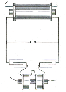
A spark gap transmitter is basically composed of two capacitors (electrical apparatus designed to store electrical energy). However, the switch that ultimately forms the connection between the two capacitors is ionized gas (the air gap) that facilitates the passage of an oscillating current from one side of the transmitter (from one capacitor) to the other.
In normal conditions, the air gap forms a barrier between the two capacitors. To break the gap, a spark must be induced. To this end, the capacitor that is directly connected to a power source is charged with electricity. The electrical charge does not immediately dissipate because of an in-built resistor that 'holds' the charge.
After the electrical charge reaches the minimum threshold voltage, the electric charge passes through the resistor to the conductive electrode touching the air gap. This electrode subsequently releases the charge towards the gap and this ionizes the air within the gap; this forms a connection between the two electrodes at the gap.

This initial spark makes the air gap conductive and the pulse generates an electromagnetic wave in the radio frequency range (around 350,000 Hz). This transforms the spark-gap transmitter into a resonant circuit (an inductor-capacitor setup) where alternating current is conducted. This process is very similar to what happens when the negatively charged particle from the air touches the positively charged particle on land in a lightning flash.
Very soon after the initial spark, though, the wave weakens since some of the energy escapes though the antenna found on the side of the second capacitor and some are used up due to resistance. At a certain point, the ionized gas builds up resistance once again and the flow of current stops. Since the radio wave is weakened after a while, spark-gap transmitters acquired the name 'damped oscillation' transmitters.
A typical spark gap transmitter is powered by high voltage transformers feeding AC power. The latter allows the capacitor to charge quickly and in a fixed cycle which can be controlled to allow for 'pulsing' radio signals.
History of Spark-Gap Transmitters
In a way, spark-gap transmitters may have been the key to the development of wireless transmission. In 1862, James Clerk Maxwell predicted that electromagnetic waves can travel through a vacuum; in 1888, Heinrich Hertz used a spark-gap transmitter and a spark-gap detector to prove that the transmitter was producing electromagnetic waves – every time the transmitter sparked, small sparks were observed in the receiver's spark gap.
Guglielmo Marconi, inspired by the experiments of Hertz and others (including Nikola Tesla), was able to develop practical and workable wireless telegraphy using high-powered spark-gap transmitters. Though they could not be used for voice transmission, spark-gap transmitters still became the standard equipment for the military and the maritime industry.


Follow Us!