A high-frequency alternator is an electrical device used for radio communications. It yields high-frequency, periodically alternating current that can go as high as 100,000 Hz for the purpose of producing stable radio waves.
The History of High-Frequency Alternators
By the first decade of the 20th century, wireless telegraphy was already in place and was no longer a novelty. The problem, however, was that the primary means of wireless communication – the spark-gap transmitter – was seen to pose major problems. For one, communications took place through the Morse Code system.
Aside from being unsuitable for voice transmissions, spark-gap transmitters sent out exceedingly varied frequencies and thus generated signals that were too strong that they drowned out other signals or too weak that they could not be deciphered.
In late 19th century, it was speculated that if an electrical alternator could be run at sufficiently fast speeds, radio waves could be generated. The theory was tested and proven practicable by various engineers and scientists including Nicola Tesla, who was initially able to create an alternator that produced current in the range of 10,000 Hz and very low frequency radio waves. Tesla later on produced radio signals with constant frequency and amplitude through 50,000 Hz rotations.
Years later, Canadian inventor Reginald Fessenden collaborated with General Electric for a 100-KHz voice transmission capable alternator. Alexanderson made a working machine that was too cumbersome for ship-borne operations but was perfect for land-based ones.
How a High-Frequency Alternator Works
An alternator generates electricity by having a "rotor" (actually a rotating magnet) turn within a "stator," an unmoving set of conductors (e.g. steel wires) wrapped around an iron or steel core. As the magnetic field from the rotating magnet cuts across the conductors, electrical current is generated.
The high-frequency alternator works on the same principle. It has a circular stationary component made of iron. This stator has slots on which are affixed two groups of C-shaped coils. One group of coils is fed direct current. This produces within the air gap a magnetic field.
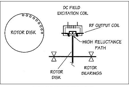
In the stator's air gap where the magnetic field is present, a rotating disc rotor passes through. This disc rotor is peppered with regularly spaced holes or gaps which are packed with non-magnetic components to prevent air from getting trapped; air can reduce rotational speeds.
While rotating, a part of the rotor is always within the air gap. If the rotor' iron part is in the gap, the field goes through; the solid iron part lets magnetic field through towards the secondary coils. If the hole is in the air gap, the non-magnetic stuffing disrupts the magnetic field so the amount of magnetic force received by the second coil is significantly reduced.
The fluctuating magnetic field in the second group of coils stimulates the production of voltage in the secondary coils. This leads to the production of radio signals in an attached antenna. The constant speed of the rotor's rotation ensures consistent radio signal strength. This radio signal can be adjusted, if necessary, through magnetic amplification.

Follow Us!