The OSI Model was created based on recommendations from the International Organization for Standardization (ISO) in 1980, which started expanding on the DoD model in the late 1970s. The current standard was published in 1996. The official title for the model is the ISO OSI (Open Systems Interconnection) Reference Model since it describes or relates to connecting systems that are open for communication with other systems. In the model, the functions of the communication system are standardized by categorizing them into abstract layers. The functions which are similar are grouped into the same layer and provide services to the layers above their existing layer.
What Does the OSI Model Do?
The OSI model depicts how data communications should take place. It splits the functions or processes into seven groups that are described as layers. When protocols or other standards are developed by other organizations such as the American National Standards Institute (ANSI), Institute of Electrical and Electronic Engineers (IEEE), and the International Telecommunications Union (ITU) formerly known as the CCITT (Comite Consultatif Internationale de Telegraphique et Telephone), they are placed into a layer of the model to help with communication protocol integration and conceptual understanding. The majority of major network and computer vendors, large commercial entities, and governments support the use of the OSI model. Each of the layers of the OSI model is intended to function with those above and below it respectfully within the model definition.
The OSI model defines standards for:
- The way in which devices communicate between each other.
- The means used to inform devices when to send data and when not to transmit data.
- The methods which ensure that devices have a correct data flow rate
- The means used to ensure that data is passed to, and received by the intended recipient.
- The manner in which physical transmission media is arranged and connected.
What Are the Seven Layers of the OSI Model?
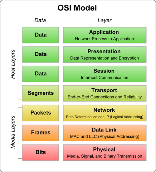
The OSI model is made up of seven layers which are presented as a stack. Each of the layers of the OSI model has a numerical level or layer, and a plain text descriptor. Data which is passed over the network moves through each layer.
The seven layers of the OSI model are:
- Application Layer – layer 7
- Presentation Layer – layer 6
- Session Layer – layer 5
- Transport Layer – layer 4
- Network Layer – layer 3
- Data-Link Layer – layer 2
- Physical Layer – layer 1
A common mnemonic used to remember the OSI model layers starting with the seventh layer (Application) is: “All People Seem to Need Data Processing.” The lower two layers of the model are normally implemented through software and hardware solutions, while the upper five layers are typically implemented through the use of software only.
Each layer of the OSI model has its own unique functions. The process of sending data is typically started at the Application layer, is sent through the stack to the Physical layer, and then over the network to the recipient. Data is received at the Physical layer, and the data packet is then passed up the stack to the Application layer.
Different protocols operate at the different layers of the OSI model. Each layer of the OSI model has its own protocols. TCP and IP are collectively called the protocol stack or the network/transport protocols. This is due to the protocols operating at the Network and Transport layers to make it possible for computers to communicate. A protocol stack, r stack, is a group of protocols which are arranged in layers to enable communication. In the protocol stack, each layer provides services to the layer above it; and each layer also receives services from the layer beneath it. For two computers to partake in communications, each computer has to be running the same protocol stack. They can however have different operating systems.
The published “advantages” of the OSI Model are: enhanced learning/teaching, reduced intricacy, modular engineering, interoperable technology, accelerated advancement, and standard interface definitions. Unfortunately; however, the OSI Model has not been found to map well to real world networking implementations or issues as the technical world has evolved. It is the most recognized model; however, and is still often used to describe networking protocols, gear, problems, and solutions.
What Are the OSI Model Layer Functions?
Layer 7 – Application
The Application layer is the highest layer of the OSI model, and it provides the interface between the network protocol and the software running on the computer. The Application layer provides the necessary services that support applications. It provides the interface for e-mail, Telnet and File Transfer Protocol (FTP) applications, and files transfers. This is the location where applications interrelate with the network
The common application protocols include:
- File Transfer Protocol (FTP)
- Telnet
- Simple Mail Transfer Protocol (SMTP)
- Internet Message Access Protocol (IMAP),
- Post Office Protocol (POP)
- Hypertext Transfer Protocol (HTTP)
- Simple Network Management Protocol (SNMP).
- Network News Transfer Protocol (NNTP)
Layer 6 – Presentation
The Presentation Layer’s primary responsibility is to define the syntax that network hosts use to communicate. Compression and encryption fall in the functions of this layer. It is sometimes referred to as the “syntax” layer and is responsible for transforming information or data into format(s) the application layer can use.
The functions performed at the Presentation layer of the OSI are:
- Protocol conversion
- Data translation.
- Data encryption and decryption
- Data compression
- Character set conversion
- Interpretation of graphics commands.
Data is translated at the Presentation layer when it is transmitted from the sender to the receiver. The application of the sender moves the data to the Presentation layer. The Presentation layer translates the data to a common format which can be read by both computers. When the data is received, the Presentation layer translates the data to a format which the application can read.
Gateway services also function at the Presentation layer. A gateway can be defined as a connection point between networks which run different systems and applications. Gateways are typically deployed through software. An example is Gateway Services for NetWare (GSNW).
Common gateways include:
- Gateways which cross platforms and file systems
- Systems Network Architecture (SNA) gateways enable PCs to communicate with mainframe computers.
- E-mail gateways enable data to be transmitted between different e-mail applications running the same protocol.
Layer 5 – Session
The Session Layer establishes process to process communications between two or more networked hosts. Under OSI, this layer is responsible for gracefully closing sessions (a property of TCP) and for session check pointing and recovery (not used in IP). It is used in applications that make use of remote procedure calls. The Session layer utilizes the virtual circuits created by the Transport layer to establish communication sessions.
The important functions performed at Session layer to establish, maintain and terminate communication sessions are summarized below:
- Establishes, terminates, and monitors communication sessions between applications
- Name lookup and security functions.
- Placement the header information in a packet which determines the point where a message starts and the point where a message ends.
- Data synchronization. The layer performs synchronization between the Session layer of the data sender and the Session layer of the receiver of the data.
- Controls whether the communication or messages being exchanged in a session are transmitted as full duplex messages or half duplex messages.
- Full duplex: Information is transmitted simultaneously, and in both directions.
- Half duplex: Information is transmitted in both directions, and flows in one direction at a time.
Layer 4 – Transport
The Transport Layer is responsible for the delivery of messages between two or more networked hosts. It handles fragmentation and reassembly of messages and controls the reliability of a given link.
The important functions performed at the Transport layer to enable network communication are listed below:
- Guaranteed data delivery
- Name resolution
- Flow control
- Error detection
- Error recovery
The Transport layer at each computer verifies that the application transmitting the data is actually allowed to access the network. It also verifies that each end of the network connection can start the data transfer process. The transport protocols running on each host partaking in communication monitors the data transfer process, and monitors for errors as well.
The common Transport protocols utilized at this layer are:
- Transmission Control Protocol (TCP): TCP is a connection-orientation protocol that offers greater reliability when it comes to transporting data than what UDP, the other TCP/IP protocol which works at this layer provides. With TCP, the application which sends the data receives acknowledgement or verification that the data was actually received.
- User Datagram Protocol (UDP): UDP is a connectionless protocol that does not provide reliable data transport. No acknowledgements are transmitted.
Layer 3 – Network
The Network Layer is primarily responsible for establishing the paths used for transfer of data packets between devices on the network. Network routers operate at this layer which can commonly be divided into three sub-layers: Sub network access, Sub network-dependent convergence, and Sub network-independent convergence.
One of the main functions performed at the Network layer is routing. Routing enables packets to be moved among computers which are more than one link from one another.
The functions performed at the Network layer of the OSI model are listed below:
- Traffic direction to the end destination
- Addressing; logical network addresses and services addresses
- Routing functions; route discovery and route selection
- Packet switching
- Packet sequence control
- End-to-end error detection, from the data sender to the receiver of data.
- Congestion control
- Network layer flow control and Network layer error control
- Gateway services
Layer 2 – Data Link
The Data Link Layer is primarily responsible for communications between adjacent network nodes. Network switches and hubs operate at this layer which may also correct errors generated in the Physical Layer.
The Data-link layer of the OSI model enables the movement of data over a link from one device to another, by defining the interface between the network medium and the software on the computer. The Data-link layer maintains the data link between two computers to enable communications.
The responsibilities of the Data-link layer include:
- Packet addressing
- Media access control
- Format the frame used to encapsulate data
- Error notification on the Physical layer
- Managing of error messaging specific to the delivery of packets.
Ensures that frames are transmitted from one computer to another computer with no errors. It establishes error-free connections between two devices.
Layer 2 manages the ordering of bits, packets, to and from data segments. The ensuing result is called frames. Frames contain data that is already arranged in an orderly manner. The Data-link layer receives packets from the Network layer and structures these packets into frames. The frames are then moved to the Physical layer for sending. A cyclic redundancy check (CRC) is added to the data frame. The CRC detects damaged frames. The computer at the receiving end can request the cyclic redundancy check (CRC) so that it can verify that the frame is not damaged. The Data-link layer can determine when a frame is lost. It also requests any lost frames to be retransmitted. By performing these tasks, the Data-link layer makes it possible for data bits to be transmitted in an organized manner.
The Data-link layer is divided into the following two sublayers:
- Logical Link Control (LLC) sublayer: The LLC sublayer provides and maintains the logical links used for communication between the devices.The functions at the LLC sublayer of the Data-link layer include the following:
- Error checking
- Frame synchronization
- Flow control
- Media Access Control (MAC) sublayer: The MAC sublayer of the Data-link layer controls the transmission of packets from one network interface card (NIC) to another over a shared media channel. A NIC has a unique MAC address, or physical address. This address identifies the particular NIC on the network. To ensure that these addresses are unique, the MAC addresses are usually permanently burned in the memory of the NIC. The MAC sublayer handles media access control which essentially prevents data collisions. It provides for the allocation of network access to computers, and more importantly, it prevents computers from transmitting data simultaneously.The common media access control methods are listed below.
Layer 1 – Physical
The Physical Layer handles the bit level transmission between two or more network nodes.
The first layer in the OSI model is the Physical layer which transmits raw bit streams over a physical medium. The Physical layer deals with establishing a physical connection between computers to enable communication. The physical layer is hardware specific and deals with the actual physical connection between the computer and the network medium. All devices that function at the Physical layer handle signalling. Data handled at the layer are in bits (1s and 0s). The 1s and 0s are in represented by pulses of light or electricity. Components in this layer include connectors, cable types, pin-outs, and voltages which are defined by the applicable standards organization.
The details on the actual physical connection defined at this layer include:
- Physical topologies of the network.
- Network connection types and how cable is attached to the Network Interface Card (NIC).
- Data encoding: This relates to the analog and digital signaling methods utilized to encode data in the signals.
- Bit synchronization
- Multiplexing
- Termination
The specifications of the Physical layer include:
- Physical layout of the network
- Voltage changes and the timing of voltage changes.
- Data rates
- Maximum transmission distances
- Physical connectors to transmission mediums
The issues normally clarified at the Physical Layer include:
- Whether data is transmitted synchronously or asynchronously
- Whether the analog or digital signaling method is used
- Whether baseband or broadband signalling is used.
| Layer | Name |
|---|---|
| 7 | Application |
| 6 | Presentation |
| 5 | Session |
| 4 | Transport |
| 3 | Network |
| 2 | Data Link |
| 1 | Physical |
How Do Real World Protocols Map to the OSI Model?
The following are commonly used or implemented protocols mapped to the appropriate layer of the OSI Model (as best as they can be mapped). The problem with mapping well-known protocols to the OSI is that there is not a specific (or even general) agreement on how the protocols map to the model layers.
| Layer Name | Common Protocols |
|---|---|
| 7 Application | SSH, FTP, telnet |
| 6 Presentation | HTTP, SNMP, SMTP |
| 5 Session | RPC, Named Pipes, NETBIOS |
| 4 Transport | TCP, UDP |
| 3 Network | IP |
| 2 Data Link | Ethernet |
| 1 Physical | Cat-5 |
Understanding Network Protocols and the OSI Model
Specific protocols function at each layer of the OSI model to assist in enabling the particular layer to perform its associated functions. The network protocols enable data to be communicated between computers. When protocols function together to provide layers of the OSI model, they are referred to as a protocol suite or protocol stack.
When network protocols function together to move data between computers, the following process usually occurs:
- The data is broken into smaller chunks of data. These chunks of data are called packets.
- To identify the destination computer, addressing information is added to the data packets.
- The data is then moved to the network card for transmission over the network.
- At the receiving computer, the data packets are accepted from the network card.
- Any transmission information which was appended to the packet by the sending computer is removed.
- The packet is reassembled into the original message.
From the above process, you can see that network protocols assemble, change, and disassemble packets as data is moved through the protocol stack.
The components that make up a packet are listed below:
- Source address; this address identifies the computer sending the data.
- Destination address; this address identifies the receiver of the data.
- Information which define the manner in which the computer should send the data.
- Reassembly information.
- Packet payload; this is the data which should be sent to the destination computer.
- Error-checking information
A packet is divided into three segments, which in turn include those components which are listed above:
- Header: The header includes the following:
- A signal which indicates that data is being sent
- Source address
- Destination address
- Clock information needed for synchronization of the data transmission.
- Data: This segment of the packet contains the data which is being sent to the receiving computer.
- Trailer: The trailer segment of a packet normally includes a cyclic redundancy check (CRC) which verifies that the packet is undamaged.
A few characteristics of network protocols and protocol stacks are listed below:
- Different protocol stacks can perform network functions.
- Different types of network interface cards (NICs) can be implemented in a computer.
- A computer can have multiple NICs installed.
- A computer can at the same time utilize different protocol stacks.
- The protocol stack is connected to the network device driver for the network interface adapter by a binding process.
- Multiple protocols can be bound to the identical card.
- The binding process can be used all through the layers of the OSI model to link protocol stacks.
- If a computer has multiple interface adapters, it can have the identical protocol bound to multiple network cards.
- The device driver that function within the Data-link layer is bound the NIC.
- TCP/IP and the NWLINK Session layer can be bound to the device driver.
Computers communicate using connection-oriented protocols, and connectionless protocols.
- Connectionless protocols: A good example of a connectionless protocol is the User Datagram Protocol (UDP). Connectionless protocols provide no verification that data was delivered. These protocols operate well in networks that have a light load. Connectionless protocols tend to fail in large networks that have a heavy load.
- Connection-orientated protocols: The Transmission Control Protocol (TCP) of the TCP/IP protocol suite is a connection-orientated protocol. Connection-orientated protocols provide verification that data was delivered. These protocols guarantee the reliable delivery of data.
With reference to the OSI model, protocols are categorized as follows:
- Network protocols: These protocols deal with:
- Routing
- Addressing
- Error detection
- retransmission requests
- Transport protocols: These protocols enable sessions to be established and maintained between computers.
- Application protocols: These protocols enable:
- Applications to interact
- Data to be exchanged
The protocols stacks typically used in networks are listed below:
- TCP/IP
- AppleTalk
- NetWare
- NetBIOS
NWLink IPX/SPX
The Microsoft implementation of Novell’s IPX/SPX protocol stack is NWLink IPX/SPX. NWLink IPX/SPX is used in Novell NetWare, and is basically IPX for Windows. Windows Server 2003 includes NWLink IPX/SPX to enable Windows Server 2003 to communicate with legacy Novell NetWare servers and clients. NWLink IPX/SPX could become problematic in large networks because it does have a central IPX addressing scheme which prevents networks from utilizing the same address numbers.
The main advantages of NWLink IPX/SPX are summarized below:
- NWLink IPX/SPX is simple to implement and manage.
- Connecting is NetWare servers and clients is a simple process.
- NWLink IPX/SPX is routable
The disadvantages of NWLink IPX/SPX are summarized below:
- Windows Server 2003 only includes limited support for NWLink IPX/SPX.
- Exchanging data between different organizations via NWLink IPX/SPX is an intricate process.
- NWLink IPX/SPX does not support standard network management protocols.
TCP/IP
TCP/IP is a grouping of protocols which provides a collection of networking services. TCP/IP is the main protocol which Windows Server 2003 utilizes for its network services.
The main protocols in the TCP/IP suite are:
- Transmission Control Protocol (TCP); the protocol operates at the Transport layer.
Internet Protocol (IP); the protocol operates at the Network layer.
When communication takes place via TCP/IP, IP is used at the Network layer, and either TCP or UDP is used at the Transport layer.
The main advantages of using TCP/IP are summarized below:
- Can be used to establish connections between different types of computers and servers.
- Includes support for a number of routing protocols.
- Enables internetworking between organizations
- Includes support for name and address resolution services, including:
- Includes support for a number of different Internet standard protocols for:
- Web browsing
- File and print services
- Transporting mail
The disadvantages of TCP/IP are summarized below:
- IPX is faster than TCP/IP.
- TCP/IP is intricate to set up and manage.
- The overhead of TCP/IP is higher than that of IPX.
With TCP/IP, the TCP component of the protocol suite utilizes port numbers to forward messages to the correct application process. Port numbers are assigned by the Internet Assigned Numbers Authority (IANA), and they identify the process to which a particular packet is connected to. Port numbers are found in the packet header.
The main port numbers used are:
- Port 20; for File Transfer Protocol (FTP) data
- Port 21; for File Transfer Protocol (FTP) control
- Port 23; for Telnet.
- Port 25; for Simple Mail Transfer Protocol (SMTP)
- Port 80; for Hypertext Transfer Protocol (HTTP)
- Port 88; for Kerberos
- Port 110; for Post Office Protocol (POP3) – version 3
- Port 443; for Secure HTTP (HTTPS)
NetBEUI
NetBIOS naming is supported in Windows Server 2003. Windows Server 2003 does not though support the NetBEUI protocol. NetBEUI is a single protocol that was initially used in Windows NT 3.1 and Windows for Workgroups operating systems. The protocol provides basic file sharing services for Windows computers, and is designed for small networks. NetBEUI does not perform well on large networks. The protocol can also not support internetwork traffic because it cannot route traffic between networks. NetBEUI cannot address traffic to a computer on a different network.
What is the TCP/IP Model?
The TCP/IP (Transmission Control Protocol / Internet Protocol) was created in the 1970s by DARPA. The model came from ARPANET and is also referred to as the “Internet Model” or less frequently as the “DoD Model.” The TCP/IP model defines four abstraction layers in RFC 1122 instead of seven which describe a general set of design guidelines and implementations of specific protocols for network communication. It provides end-to-end connectivity and addresses the formatting, addressing, transmittal, routing, and how to receive data. The four layer TCP/IP model is often compared to the OSI Reference Model. A major difference between the two definitions is that TCP/IP is descriptive while the OSI Reference Model was intended to be prescriptive. The related protocols and model itself for TCP/IP are maintained by the IETF (Internet Engineering Task Force).
TCP Model Principals
In RFC 1122, the TCP model emphasized the use of communication principles over the layering concept fundamental to the OSI. These principles include end-to-end and robustness. The original definition of the end-to-end principle assigned the maintenance of state and overall intelligence at the edges of the network and that the Internet would connect these edges while focusing on simplicity and speed. This has evolved; however, with the requirement for firewalls, web caching, network address translations, etc. and the principle continues to evolve with the modern realities. The robustness principle emphasizes conservation in sending information but liberal behavior in receiving.
TCP/IP Model Functions
The TCP/IP Model has four functions. Starting from the lowest level, these include the Physical Layer, the Link Layer, the Internet, and the transport layers.
Physical Layer – The Physical Layer consists of purely hardware and includes the network interface card, connection cable, satellite, etc.
Link Layer – Also referred to as the “Network Access Layer.” It is the networking scope of the local network connection that a host is attached. The lowest layer of IP, it is used to move data packets between the Internet Layer interfaces of two hosts on the same link. Controlling the process can be accomplished in either the software driver for the network card or via firmware in the chipset. The specifications for translating network addressing methods are included in the TCP/IP model, but lower level aspects are assumed to exist and not explicitly defined. A hierarchical encapsulation sequence is not dictated either.
Internet Layer – Handles the problem of sending data packets to or across one or more networks to a destination address in the routing process.
Transport Layer – The Transport Layer is responsible for end-end message transfer capabilities that are independent of the network. The specific tasks in this layer include error, flow, and congestion control, port numbers, and segmentation. Message transmission at this layer can either be connection-based as defined in TCP, or connectionless as implemented in the User Datagram Protocol (UDP). The Internet Protocol performs two functions:
1 – Host identification and addressing. This function uses a hierarchical addressing system referred to as the IP address.
2 – Packet routing.This is the task of moving data packets from the source to destination host by sending the information to the next router or network node that is closer to the final destination. Information can be transported that relates to a number of upper layer protocols which are identified by a unique protocol number. Some examples are IGMP (Internet Group Management Protocol) and ICMP (Internet Control Message Protocol) that perform internetworking functions which help show the differences in the TCP/IP and OSI models.
How Do the OSI and TCP/IP Models Compare?
The upper or top three layers in the OSI Model (Application, Presentation, and Session Layers) are combined into a single layer only in the TCP/IP model in the Application layer. There are some OSI protocol applications which combine the three layers such as X.400, there is not a stated requirement for the TCP/IP protocol stack to implement a discreet structure above the Transport Layer. The Session Layer corresponds to the Telnet virtual terminal functionality that is part of text based protocols like SMTP and HTTP TCP/IP model Application Layer protocols. It also corresponds to the TCP and UDP port numbering system that is part of the Transport Layer in the TCP/IP model.
There are some functions or applications that in the OSI Model are located in the Presentation Layer which is located in the Internet application layer that uses the MIME standard. This is used in Application Layer protocols such as SMTP and HTTP. Due to IETF protocol development efforts not being concerned with explicit layering of the networking models, many of their protocols do not cleanly fit into the OSI Model. These issues have been cleaned up through the publishing of annexes to the original OSI Model which makes protocols such as IGML and ICMP defined as layer management protocols for the Network Layer. The IETF protocols can also be recursively encapsulated with tunneling protocols such as the GRE (Generic Routing Encapsulation). The baseline OSI documentation does not address the technology or possibility of tunneling, but it is addressed through extensions to the model such as with the transport layer gateways defined within the International Standardized Profile network. Due to the widespread adoption of TCP/IP protocols; however, most OSI development regarding extensions has been abandoned.
How Does the TCP/IP Model Map to Real World Networking?
The TCP/IP model has become the defacto standard for real world implementation of networking. Some of the real world protocol mappings to the TCP/IP Model layers are:
| TCP/IP Model | |
|---|---|
| Application Layer | FTP, HTTP, POP3, IMAP, telnet, SMTP, DNS, TFTP |
| Transport Layer | TCP, UDP, RTP |
| Internet Layer | IP, ICMP, ARP, RARP |
| Network Interface Layer | Ethernet, Token Ring, FDDI, X.25, Frame Relay, RS-232, v.35 |
TCP/IP Model Facts
Besides being more closely grounded in the reality of modern networking, there are several facts or differences regarding TCP/IP from the more academic OSI Model:
- TCP/IP was defined after the advent of the Internet. The OSI was defined prior to the Internet.
- Service interface and protocols are loosely defined.
- The protocol is loosely layered while the OSI defines strict layering.
- TCP supports reliable delivery of data packets while UDP supports connectionless communication that is not possible in the OSI. ISO requires that all data packets be reliably delivered.
- The biggest downside to the TCIP/IP model is that the more academics teach students to reference the OSI Model, the less they will learn about the TCP/IP model actually used in industry.
What is IPv6?
IPv6 (Internet Protocol 6) is the most recent version of the Internet Protocol based on the legacy IPv4 standard. Both IPv4 and IPv6 are demultiplexed at the media layer; however, IPv6 increases the IP address size to 128 bits (from 32 bits) to support significantly more layers of addressing hierarchy, a greater overall address space, and the new concept of “Scalability of Multicast addresses.” There is also a new type of Internet address introduced in the IPv6 standard called an “Anycast Address” which is used to send information to any number of a group of network nodes. IPv6 options are located in separate data packet headers located between the IPv6 and Transport Layer headers. These changes allow for more efficient forwarding of information on the network as well as greater flexibility for introducing new options in the future that may not even be thought of today. Reading about why the OSI Model must die, go the way of Disco (isn’t that coming back in a limited degree?), and DivX: Kill the Beast: Why the Seven-Layer Model Must Die.
Hans
I believe this article has a fault at layer 5 and 6. Layer 5 session protocols are to my knowledge FTP, SMTP, HTTP, HTTPS and so on. The presentation in Layer 6 should be HTML, TXT, MIME, or any other presentation method interpreted by the application.
Schmed
No mention of IBM SNA model ? As one of those Novell guys back in the ’90s, running on 16MB Token Ring we attempted IP Tunneling for the ever too fat IPX/SPX model. We had to Bridge, not route, remote locations, and the entire network was 1 address, from an IPX/SPX perspective !!!, with 512k packet forwarding, plug a 4MB NIC into a 16MB network, or vice versa, and you took the entire local “ring” down due to a “beaconing” workstation, Oh God, what a production, and those stupid MSAU units with the IBM Type 2 connections, what a pain isolating the workstation, had to remove each MSAU, one a time, then each port (8), one at a time. Then came along this Windows NT thing, and the dethroning of Novell began. Their domain model, NDS, was no match for Microsoft’s AD, and the whole “Server as the top of the food chain” came crashing down.
Jack
A few picky items. Under What is the TCP/IP model? you said that TCP/IP was descriptive, OSI prescriptive. Effectively you have that backwards. Technically both are descriptive, but the RFCs prescribe how and what you must do to use the TCP/IP suite on the internet. The OSI/RM has always been descriptive (by definition – that’s what Reference Model means) of how networking works, and has never prescribed what you need to do. They are for different purposes.
Also, you said that the OSI was before the internet, TCP/IP after. Again, backwards. TCP/IP, in the 70s, was used by the DOD & their collaborating universities to create the DARPANET (later the ARPANET) [and TCP/IP was created bit by bit as needed to get those communications to work — prescriptive]. The OSI was written in part to help clarify all the issues that the inadequacies of the TCP/IP had in relating to other (often proprietary) systems [in other words, afterwards]. So the OSI/RM is JUST a reference model that can be used by anybody, regardless of their actual networking system.
This does not imply that one is better than the other. The OSI was designed to describe what is involved in networking so that new networking systems could be designed already knowing what would be involved. TCP/IP was created to network specific computers together, and modified as it turned out not to be generic enough for all the systems out there. Now it drives the largest [computer] network in existence. Many of the RFCs are deprecated because of specific problems, or because someone academic studied the OSI and realized potential problems. TCP/IP by nature must change constantly, the OSI might occasionally require tweaks, but was designed to be universal. Each is needed, the OSI to understand HOW networking works, the TCP/IP to be sure that one network (the Internet) works properly. If you want to hook into the internet, you do not need TCP/IP internally, but if not, you’ll need gateways. So it’s easier to design a TCP/IP network internally & you’re good to hook up to the internet when you get permission (IPs, domain name, etc).
prasad
hi
Super explanation on OSI model
Thanks.
JS
I disagree with your statement that is must die. Having learned the OSI model when beginning Networking Classes I found it very helpful in learning good troubleshooting techniques. Yes the protocols may not line up perfectly but as a learning aid there hasn’t been a better quick reference tool that I have found then the OSI model.
Schmed
I learned it when getting my Novell 3.11 CNE certification, along with IBM’s SNA Model
Yogesh Singhal
Hi,
Can anyone help me in understanding the Named PIPES protocol..what is it and how it works..with reference to SQL srver 2005?????
Thanx in advance…
anu
Hi there,
can u explain the OSI layered approach to network architecture and peer-to-peer processes with appropriate diagrams?
I dont really understand..
thank you
islam mohamed el bialy
pleas i want the answer of da following:
why the fragmentation and reassembly processes are needed ??
monkeypoison
Thank you
It has helped me with my assignment
Sasi
Data Link Layer Sublayers?
Duties of LLC and MAC sublayer?
Pete
MAC “Media Access Control”, directly related to the NIC (Network Interface Card)